I have taken a break from working on the VG1-5 project to upgrade a piece of equipment. This upgrade is being done on my little Chinese lathe. The brand name is Acra Turn and was obtain from a machine tool supplier that then went out of business, but it is just another Chinese type lathe that is available from numerous suppliers.
I initially installed a set of dro’s from CDCO out of Illinois (https://secure.sigma-star.com/cdcotools.com/index.php

They lasted less then one year, so while still under warranty the bad rail was set back. While inexpensive they were not worth the aggravation I went through to get a replacement rail. It took almost a year and numerous calls and finally a call to Home Shop Machinist ( http://www.homeshopmachinist.net/home?noredirect=true&noredirect=true) to get a new rail sent to me. HSM was great in there help and I cannot thank them enough. Also, to be honest my neighbor also bought a set of dro’s at the same time and I also obtain a second set for my other lathe and neither of the other ones have failed. When the new rail came in it was the wrong size and too large for my lathe and then the second rail failed. At this point I had just had enough.
I tried using dial indicators, but to be honest that gets a little old.

I need to make 60 of the same parts and dro’s were the only answer. About that time MSC was having a sale on Mitutoyo dro’s ( whttp://www.mscdirect.com/?cid=ppc-google-Brand+Core+–+E_sWusaD5lR_msc_e_27864417304_c_S&mkwid=sWusaD5lR|dc&pcrid=27864417304&002=2167139&004=8097512824&005=42450341&006=27864417304&007=Search&008=&025=c&026=eb ) and while more expensive then the cheaper brand it was time to order a set.

The next 9 days was an interesting trial of aggravation. This is that story.
One of the problems with the little lathe is the carriage lock. It sets right up next to the cross slide and is hard to access in normal times and impossible to access with the dro installed.

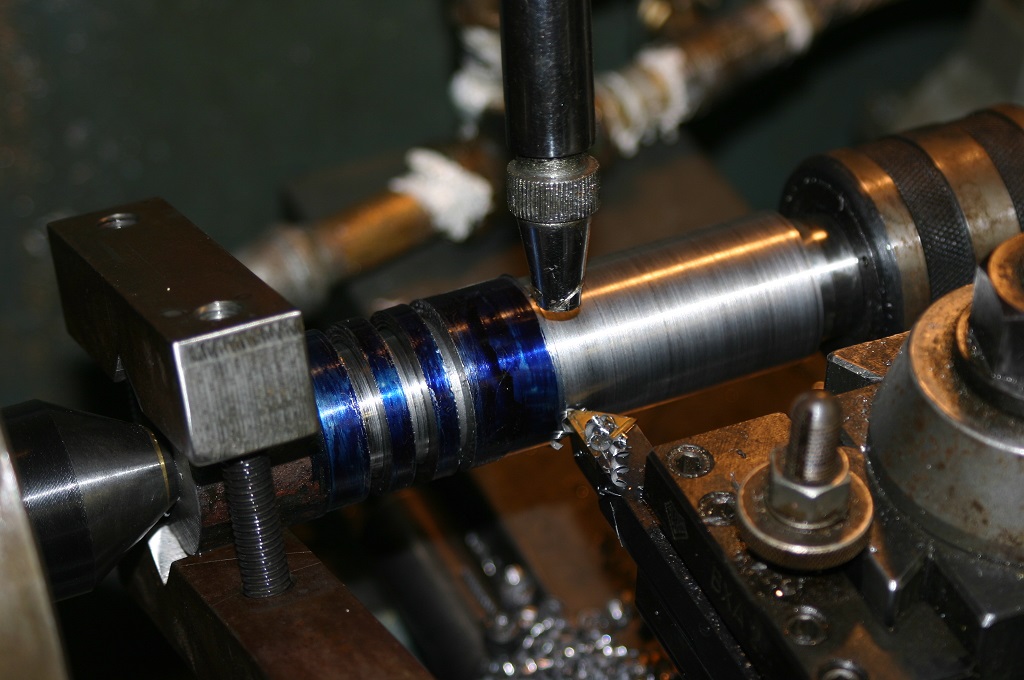
So a special lock was made to set flush on the carriage.

They still did not fit due to the height of the tool post and the height of the rails. There was no way to swing the tool post around. So now a spacer had to be made to raise the tool post.

The spacer had to be tall enough to allow the carriage lock to work and the tool post to swing around yet still not be too tall as to allow the center post of the tool post to come out of its corresponding hole. Once made it was surface ground to insure flatness.

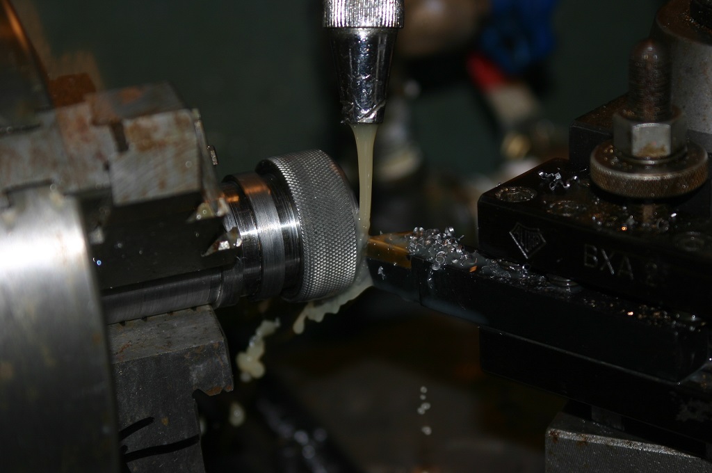
Now new hold down bolts had to be made. With the additional height the older bolts would not work. So new tee nuts were fabricated and threaded then welded in place and then ground for a smooth fit. After look for thin nuts in the shop to match the all thread it was determined that the original ones would work. With a lathe that has all metric screws these were American standard.
Installing the dro’s required a .004 run out over 40” both parallel and linear.

This was the challenge. The first attempt was to attach the dro to the side of the lathe bed and just shim to the correct run out.
This did not work. It was attempted and every time it failed. Now I decided to install an aluminum block on the side of the lathe and machine it so the block was square and eliminating the draft angle of the bed casting. I don’t ever recommend doing that. Then just a block of aluminum was attached and shims were again used. Again, not so good.

The method that worked and allow us to bring it into spec was custom made brackets.

We made a set for the head stock of the lathe and for the tail stock.

Once the dro was installed and brought into spec then the center bracket was made and installed.

After the center bracket was installed the dro was tested and still found to be in spec.

The only grip that I have is that the tie in for the wires only attach on the ends and not in the center. Thus making it difficult for the counter to set in place.

Because of the weight of the small lathe and where it sat in the shop this project would not have been possible without the industrial skates from Northern tool. These are the skates the made it possible (http://www.northerntool.com/shop/tools/product_200356890_200356890?isSearch=144020-1451).

So now the project is completed and the lathe back into it’s proper place we are back to working on the VG1-5 project. Stay tune for more updates.
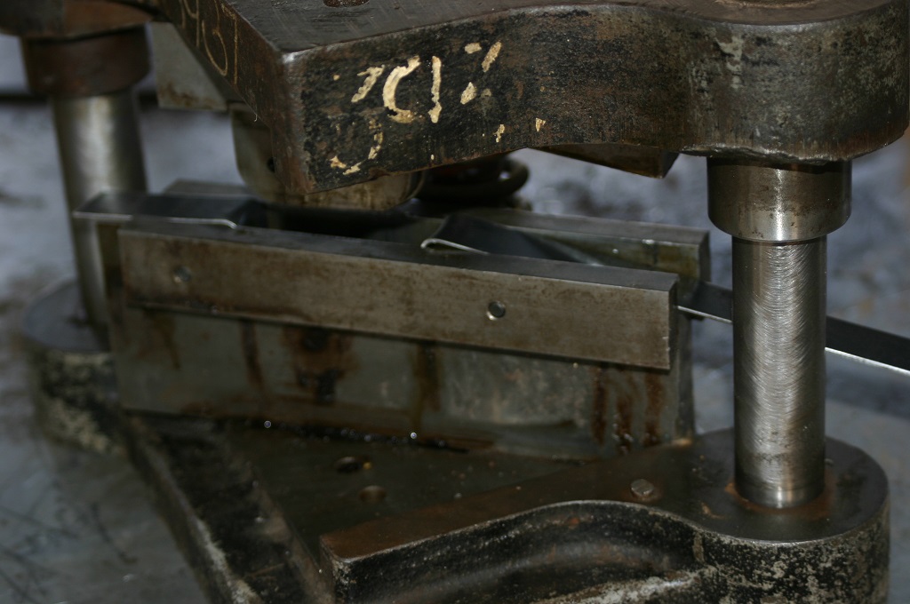
 This is how live as a pressing die started out. This same size of block was used for both the top and bottom plates.
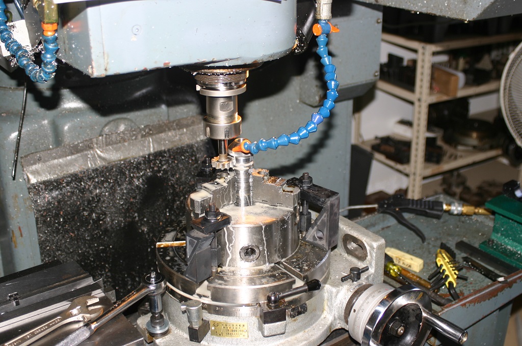
 This is how it looked after rough machining. It still needs the finish pass. That is completed with 1/4″ ball nose end mill at .008 step over. Just the finish pass will take 1 1/2 hours.
 With this picture you can see the resemblance to the actually magazine.
 This is the finish male die. All we need to do now is de-bur and mount on the die plate.