This is a quick update on the progress of the VG1-5 project.
All the bolts back from heat treat
 All the hammers back from heat treat
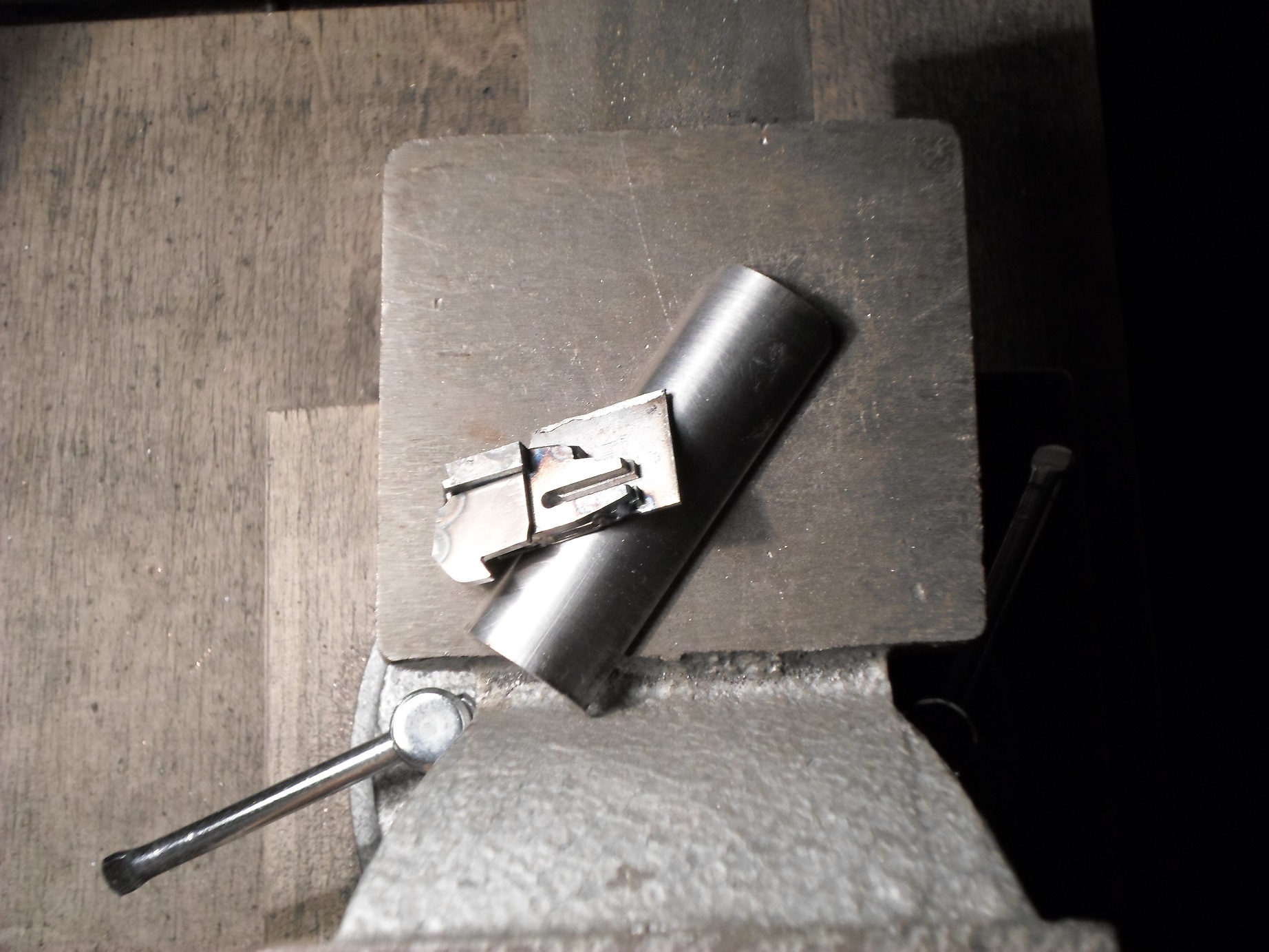
 Magazine pressings for both the right and left sides of the magazine complete, next is to mill of the excess.
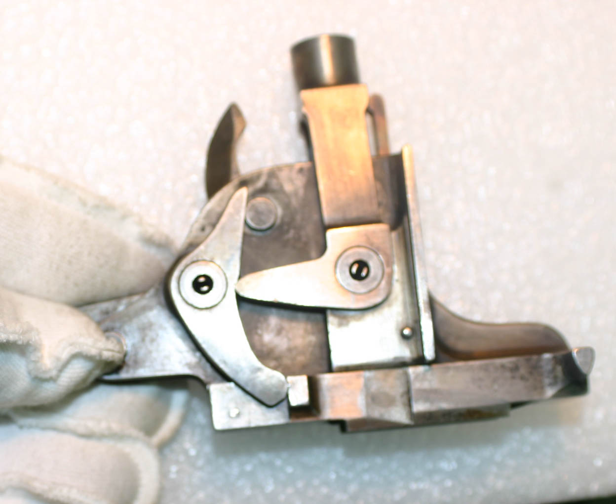
 Weld up the fire control box
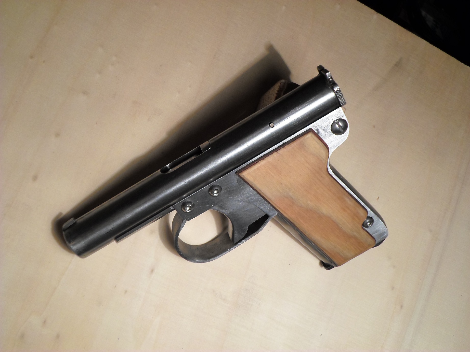
 Spot welded the rear stock supports and tack in the rear barrel support cross pin.
 Complete the welding of the cross pin.
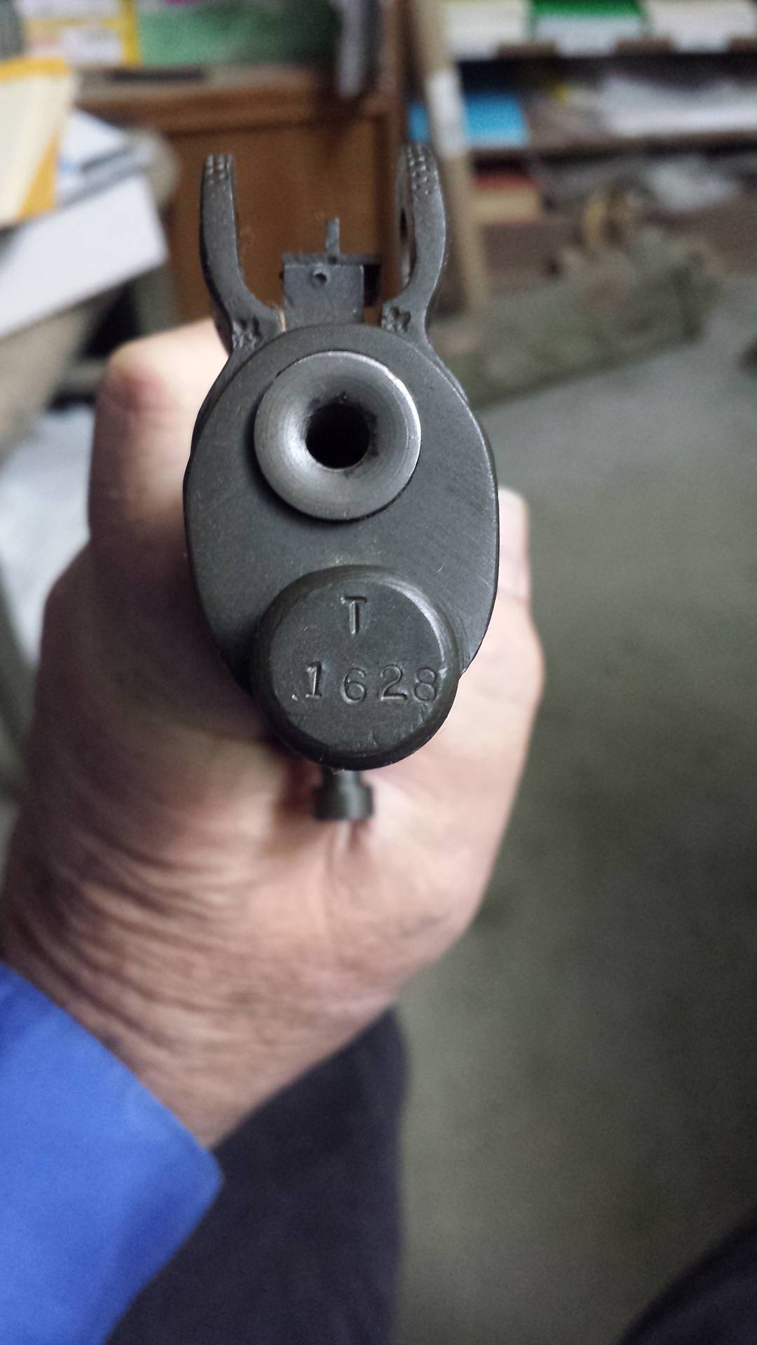
 Performing the next two ops on the barrel

 We have started chambering the barrels. The next step is to cut in the threads.
 Update video.