Looking for G-43 fire control parts. Hammer,trigger,sear. This is for one of the projects we are working on. A friend of Gun Lab has helped out with this. Thanks
|
We are now taking reservations for out reproduction VG1-5 rifles! Price is $4000, and they will be ready to ship once ATF gives final approval on the design. The get on the priority list, contact Matt or Greg at Allegheny Arsenal – (814) 362-2642. No payment will be taken until the guns are ready to ship.
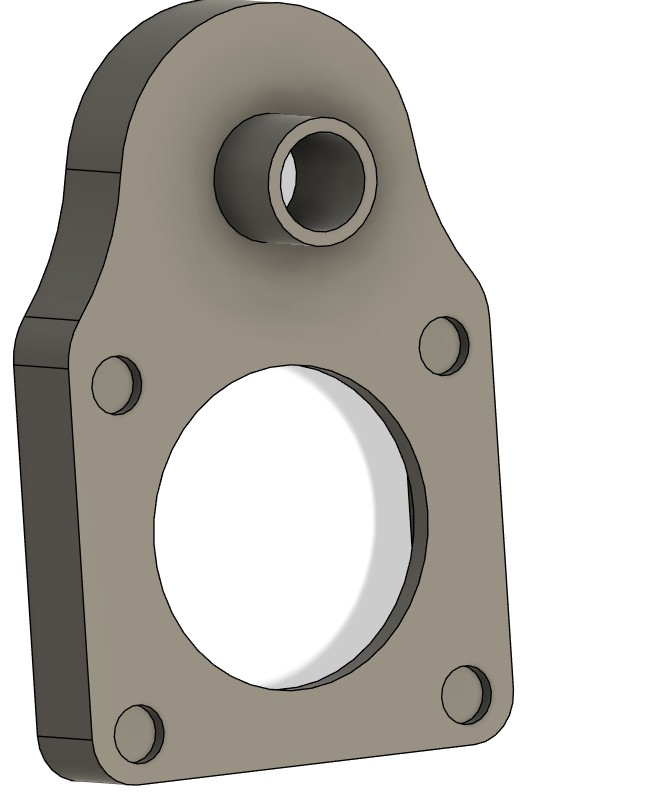
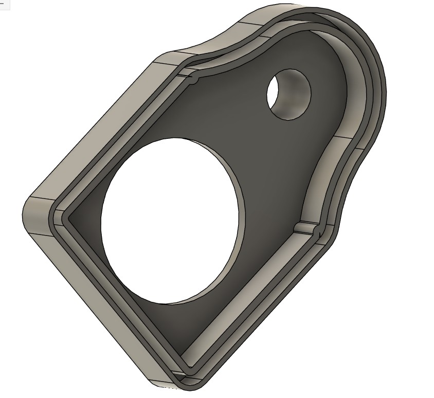
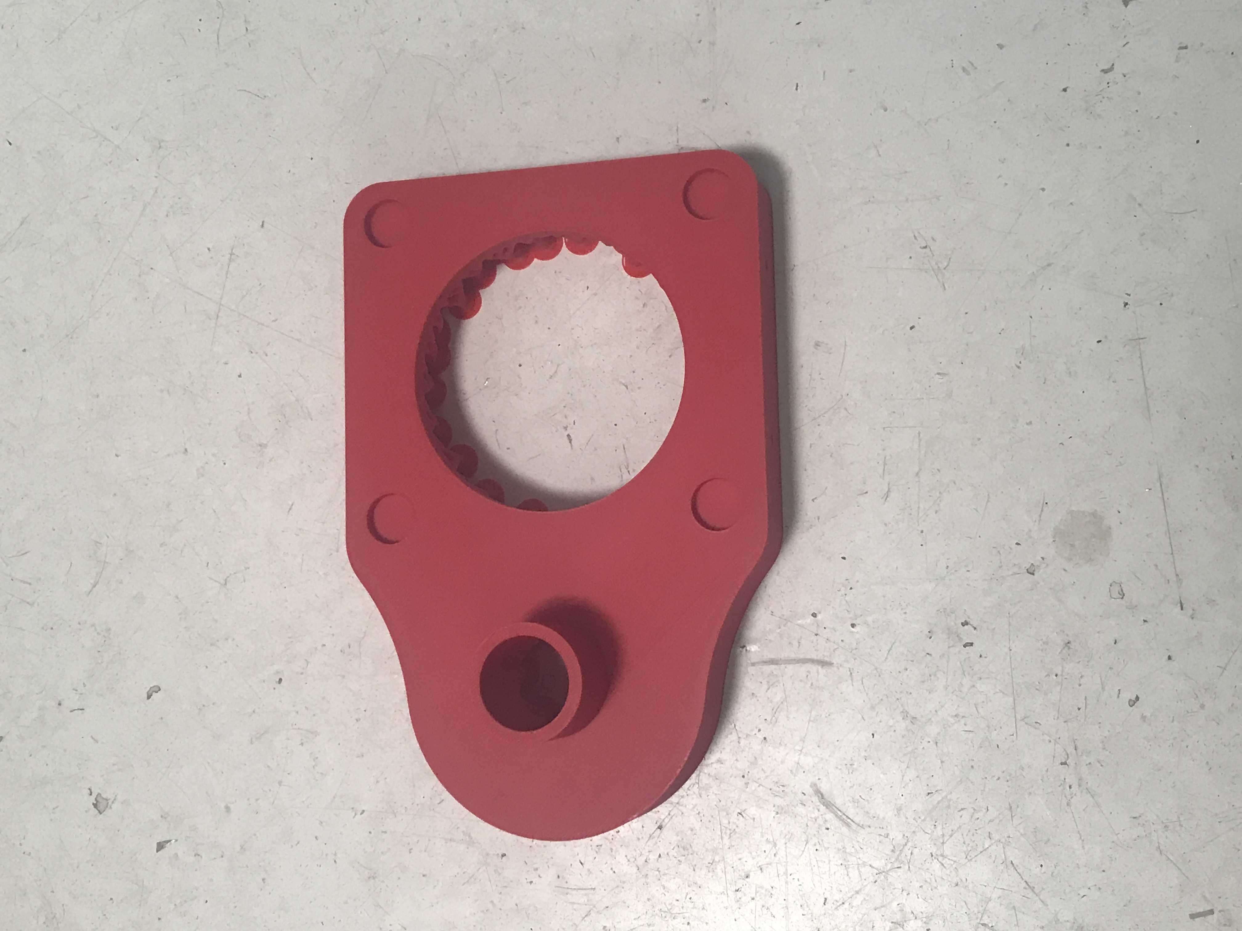
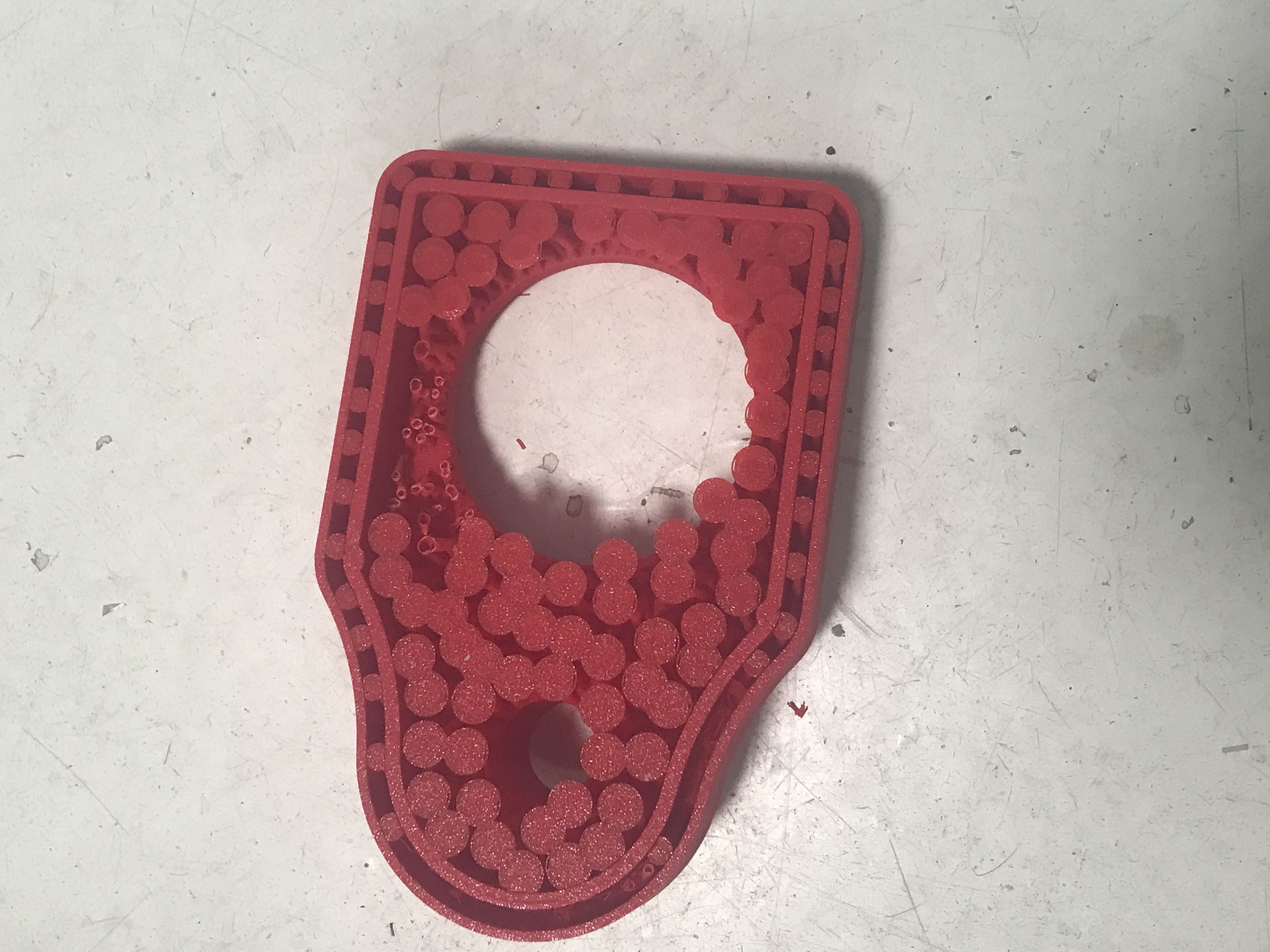
After I completed the first 3D print of the V9000 lower I notice some changes that needed to be accomplished. In fact I noticed a lot of changes that needed to be made to my solid model. some of the changes are inside dimensions and some are over all dimensions. In this case on the first print the fire control housing would not fit properly into the receiver. The walls were to thin and to far apart and the length of the receiver was not correct.
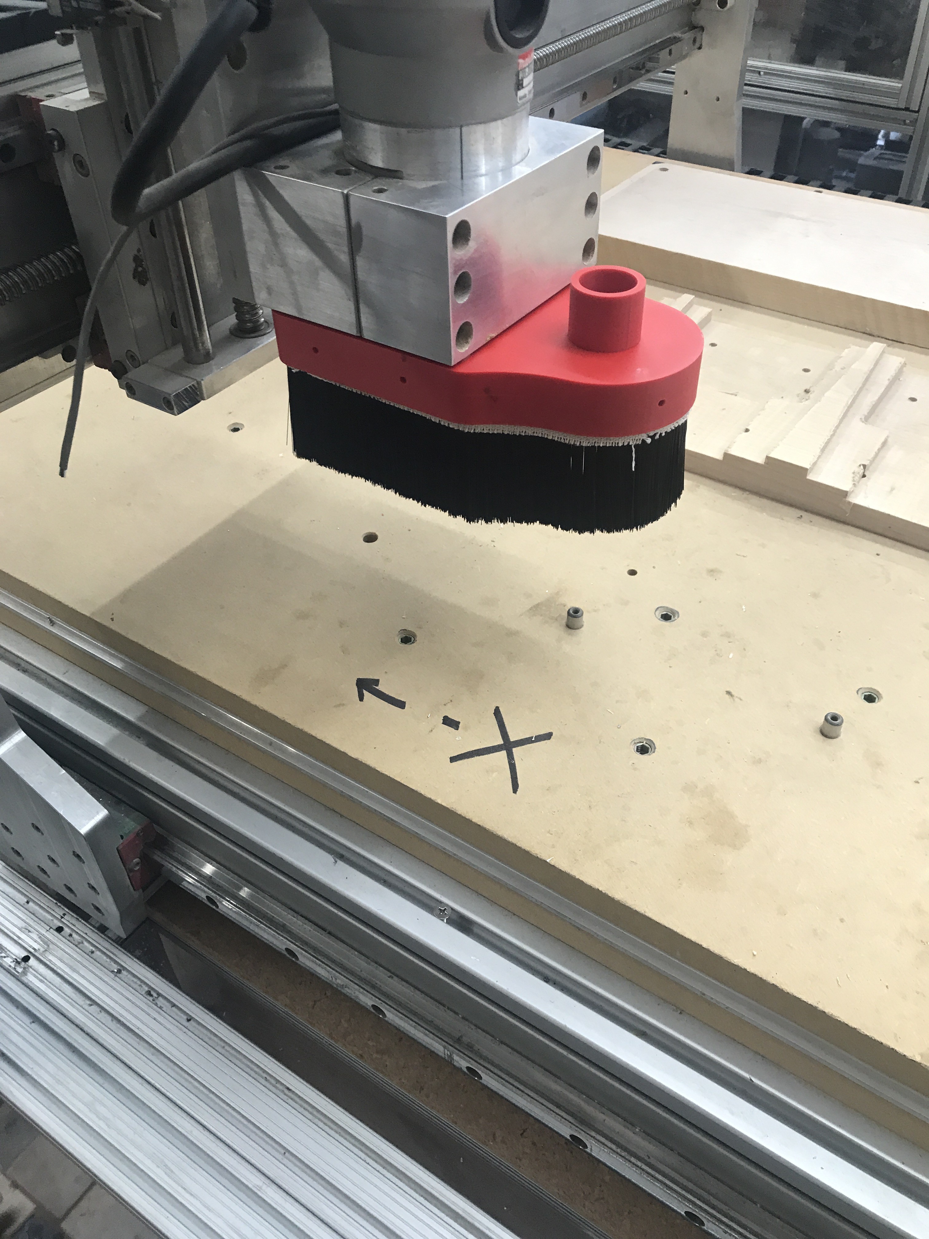
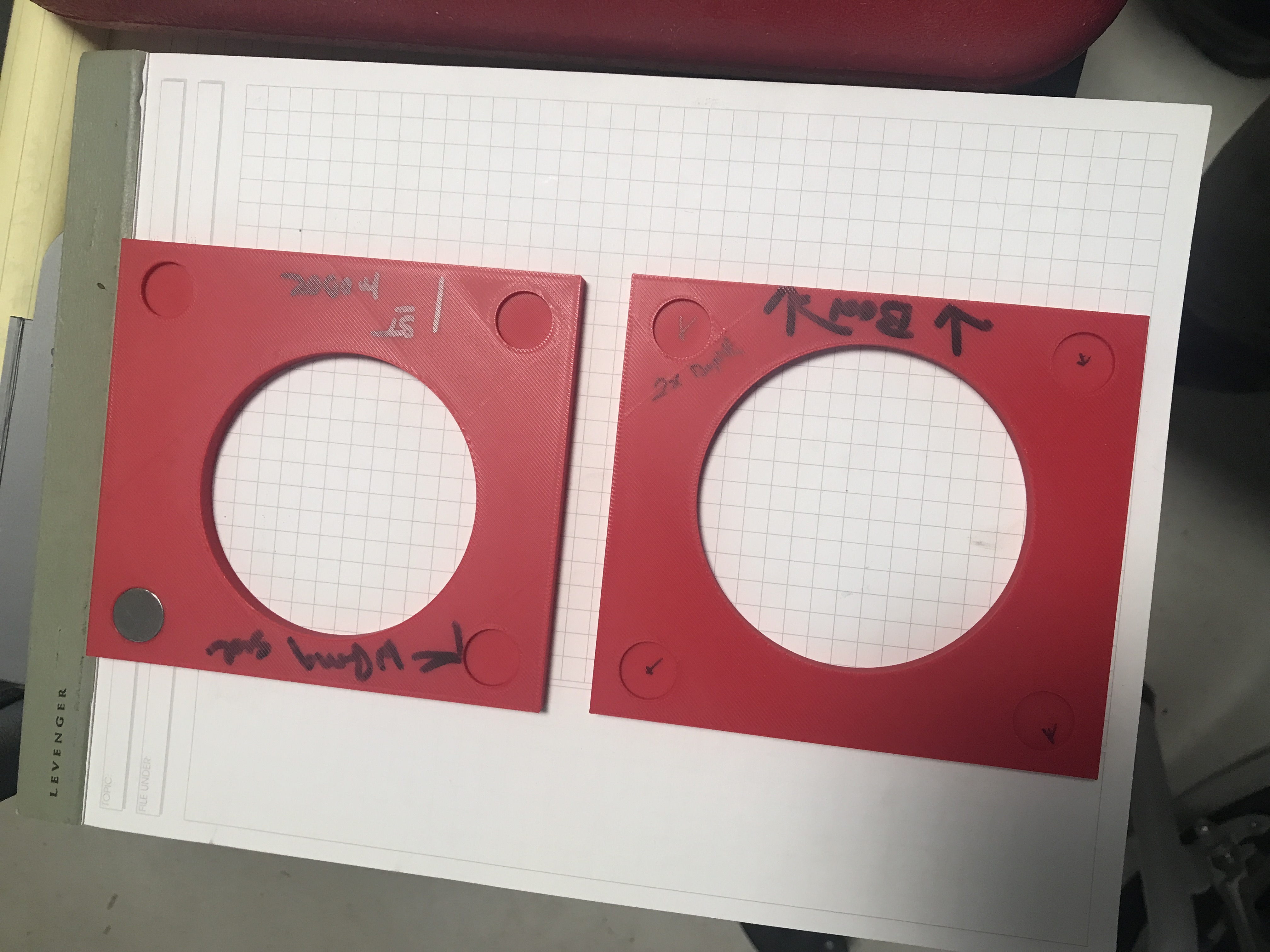
Through out the design of the cnc router boot I wanted it to be easly removable to allow for tool touch off and replacement. The only easy way to do that is with magnets. I used the second test piece that I had added cardboard spacers and then magnets that I epoxy on to the router housing frame.
Then magnets were epoxy into the boot.
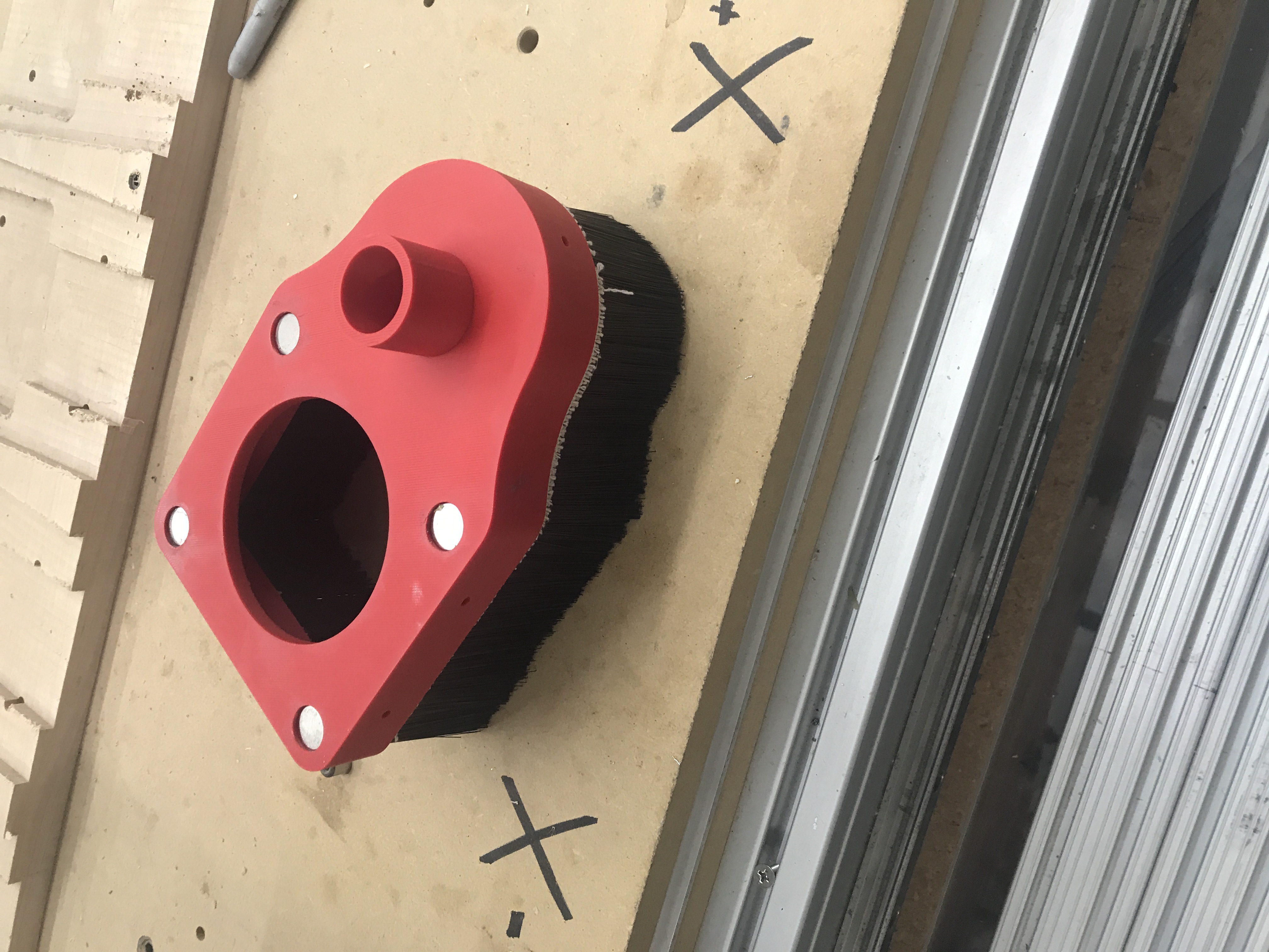
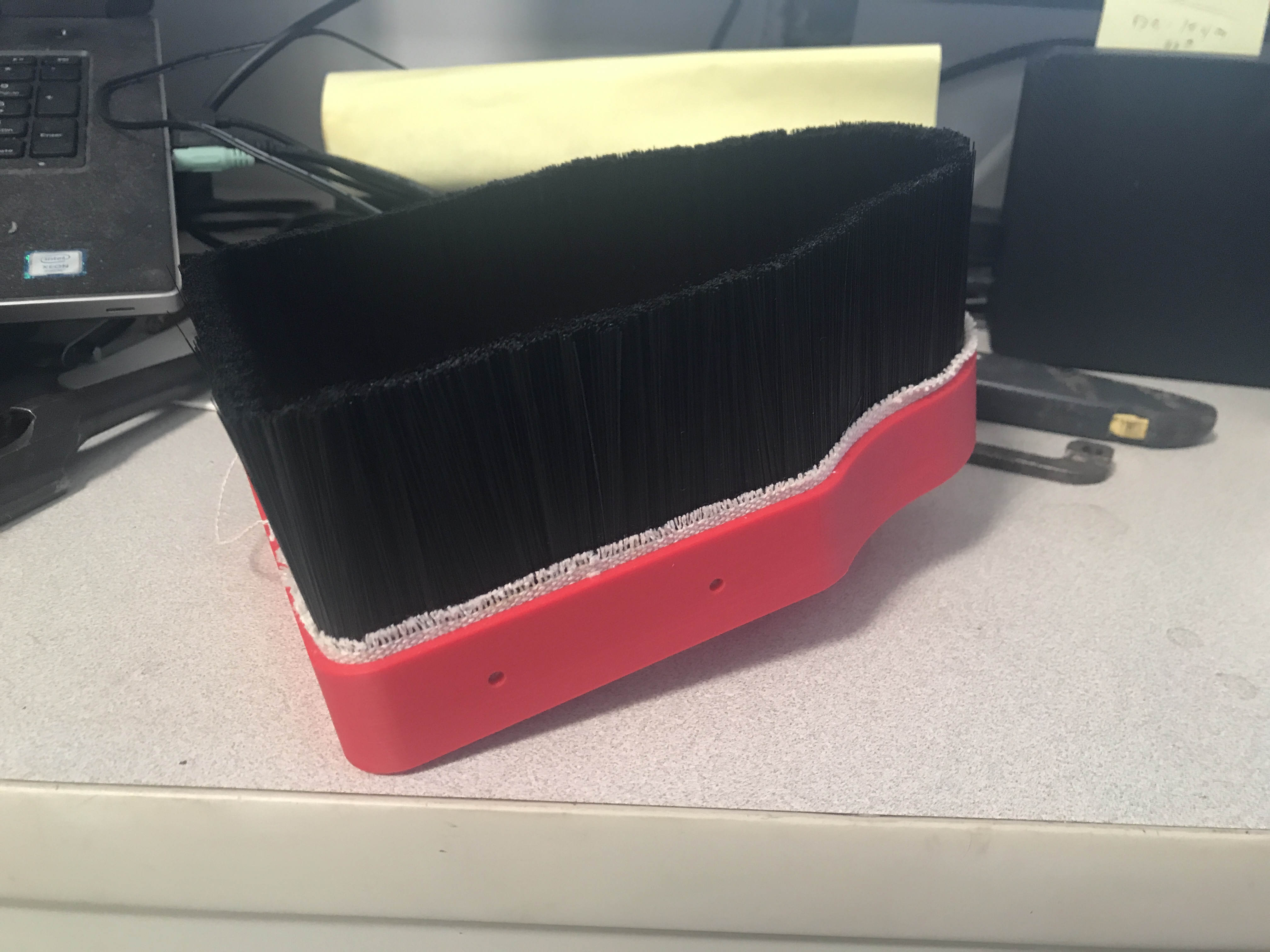
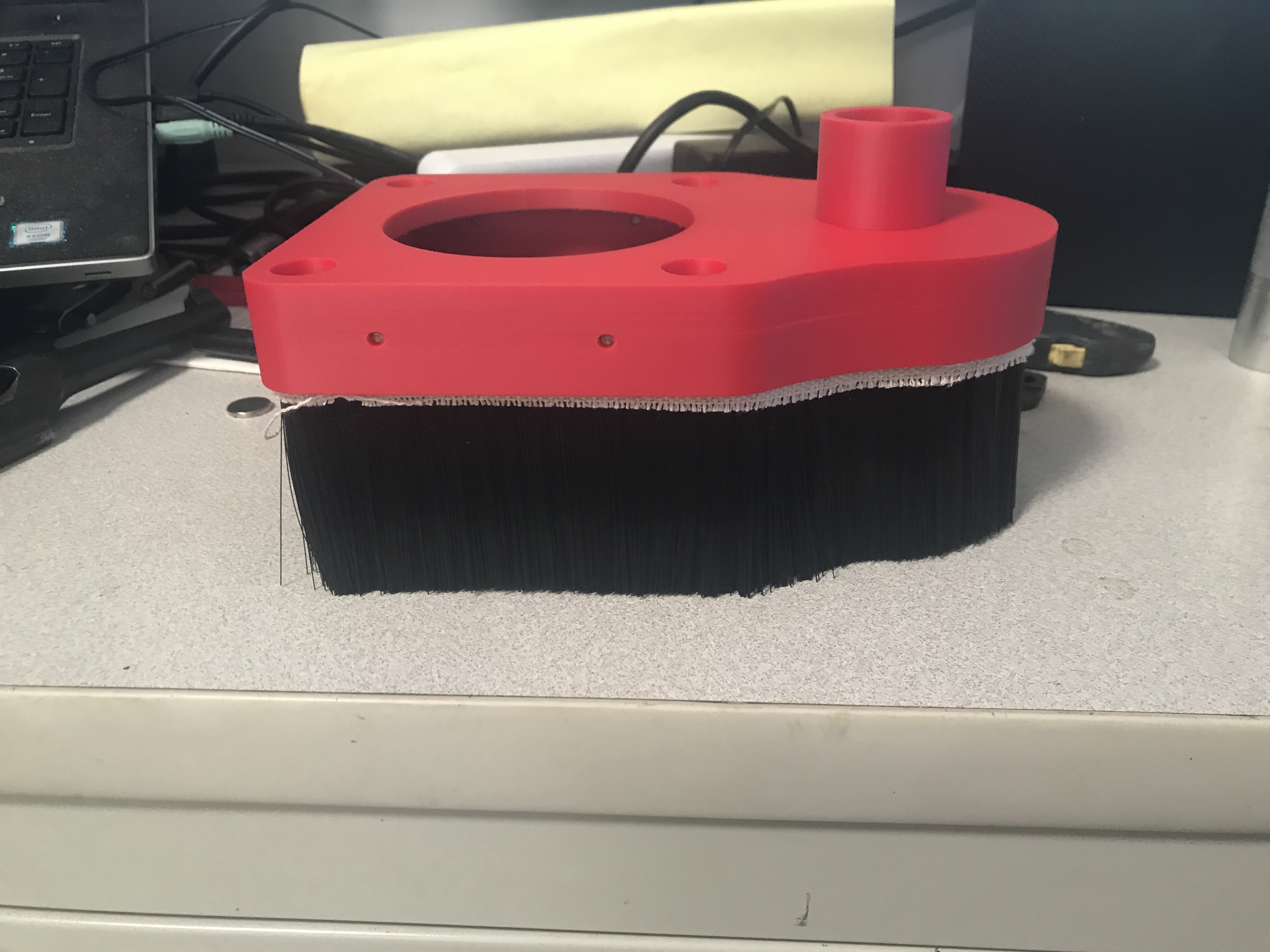
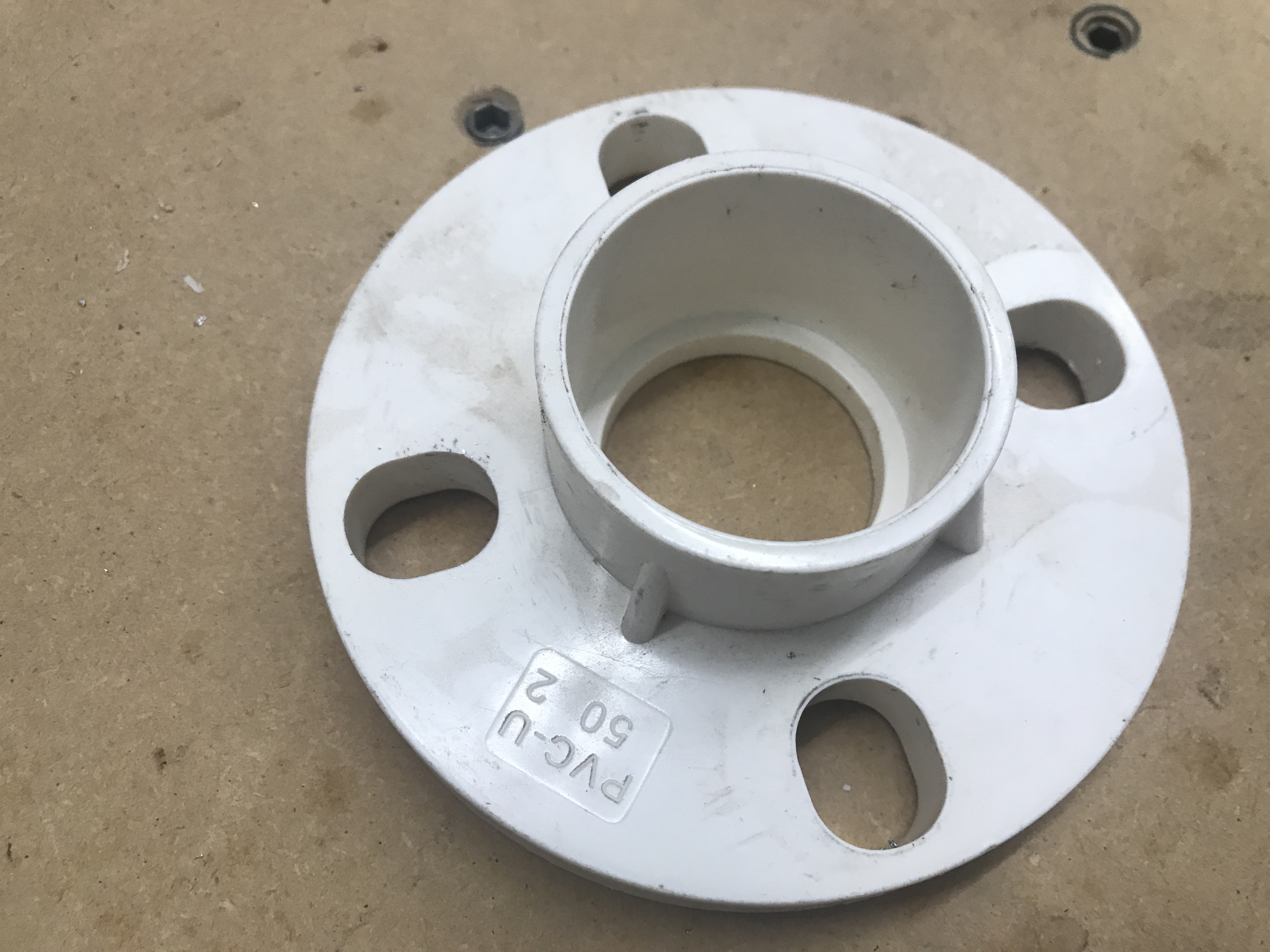
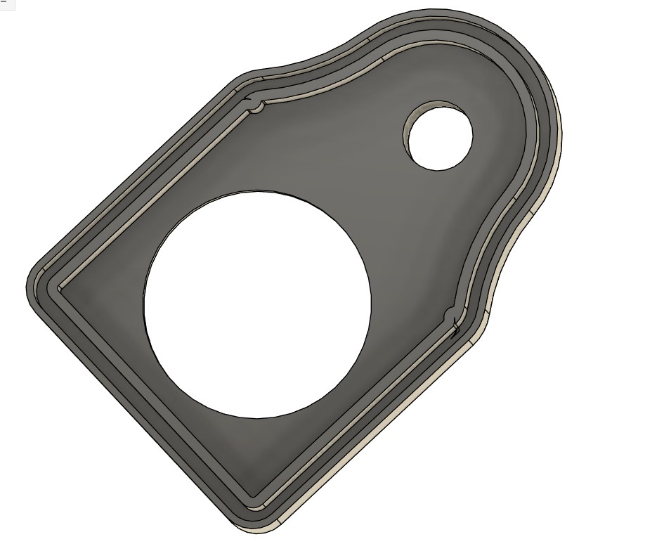
I completed the design of the cnc router dust collector boot if Fusion 360.
I printed it on the Bambu P2S 3D printer. It took 14 hours to complete the print but it did come out very nice.
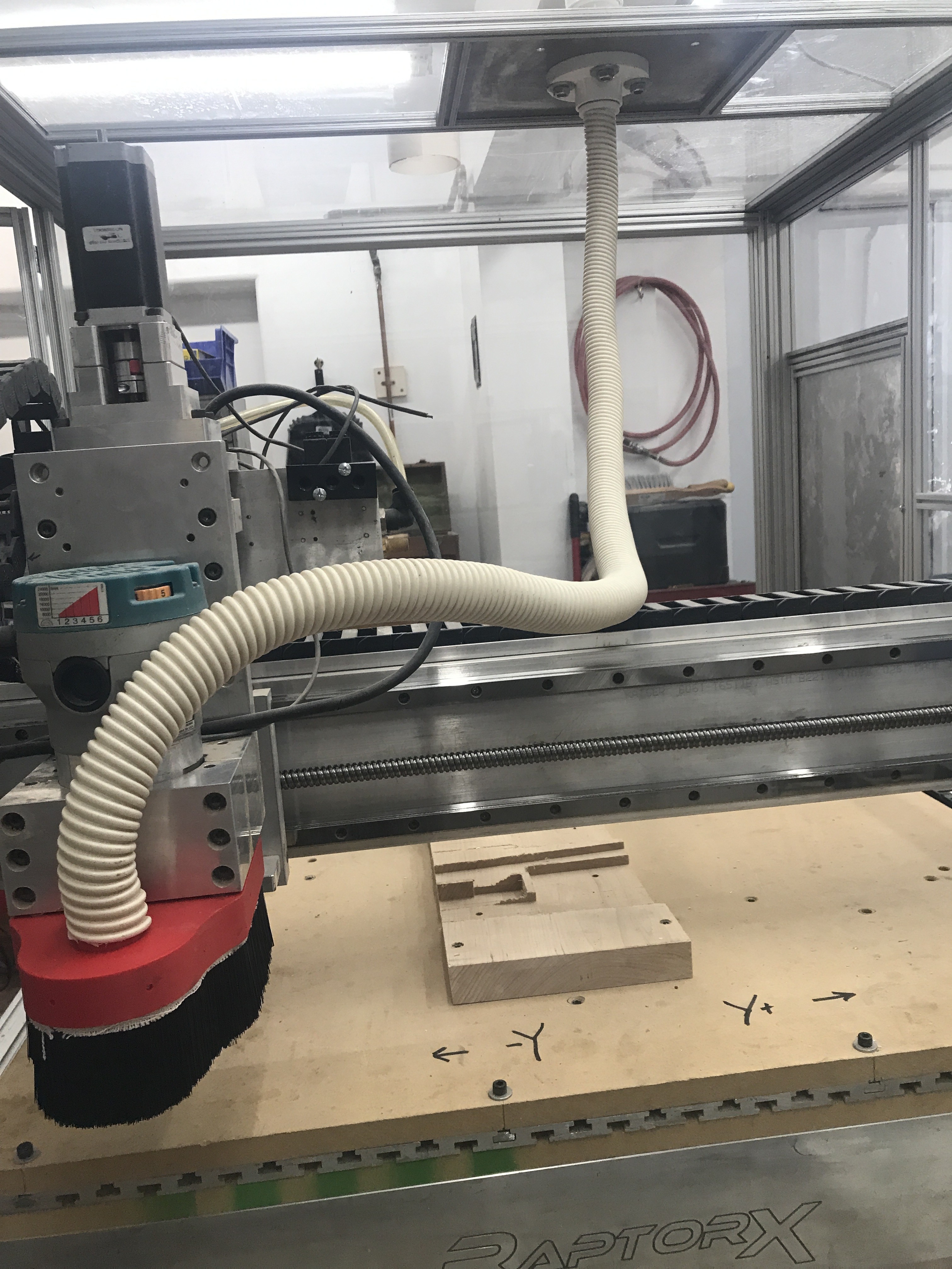
Now to install it on the cnc router.
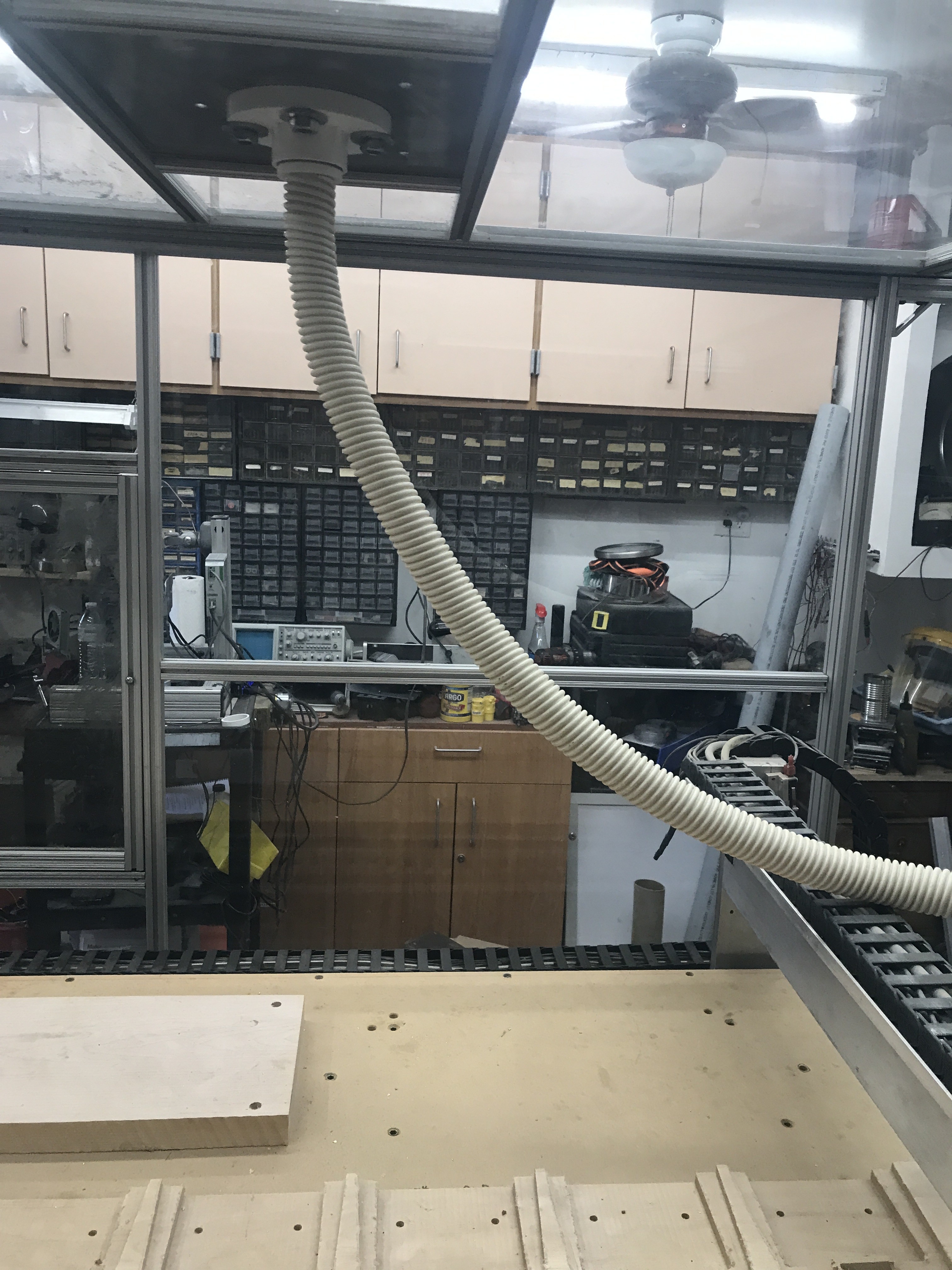
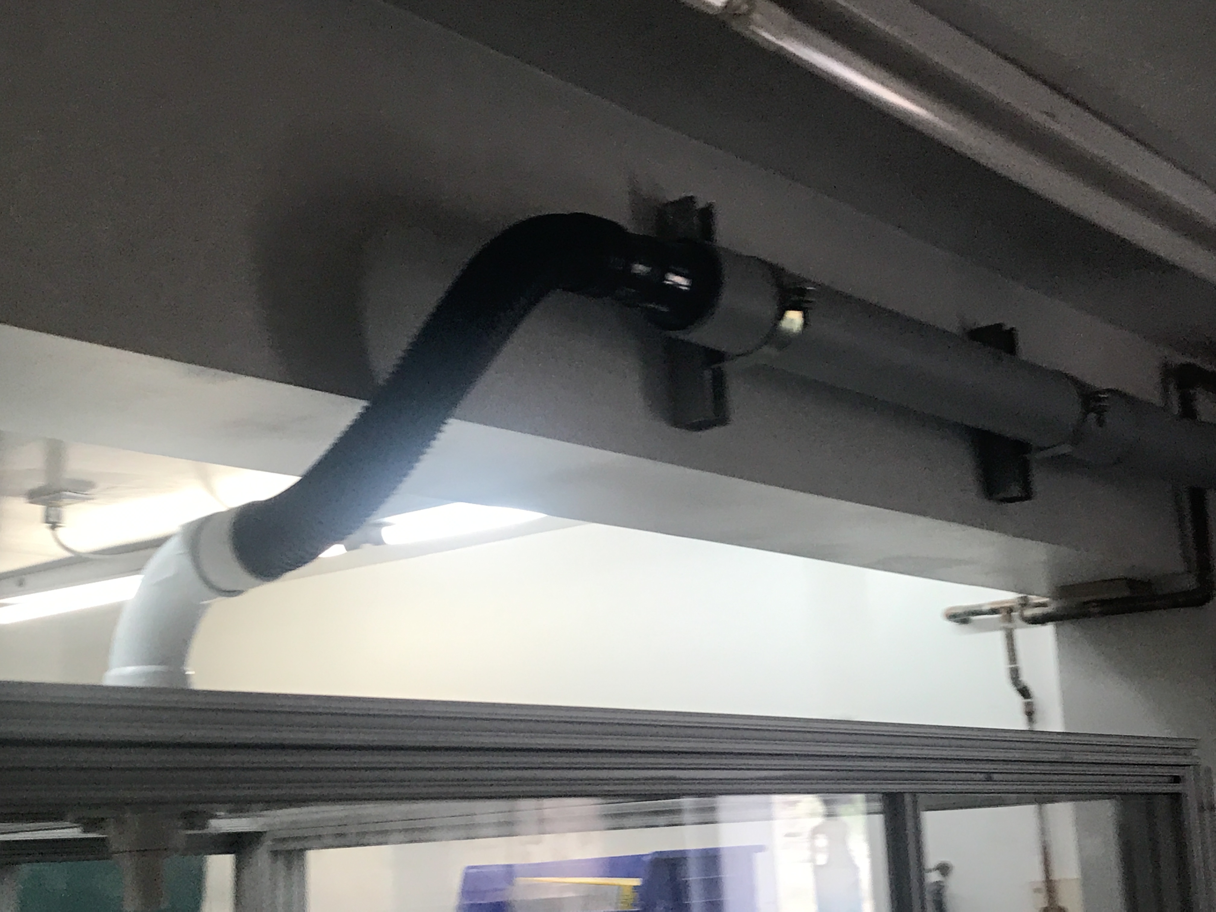
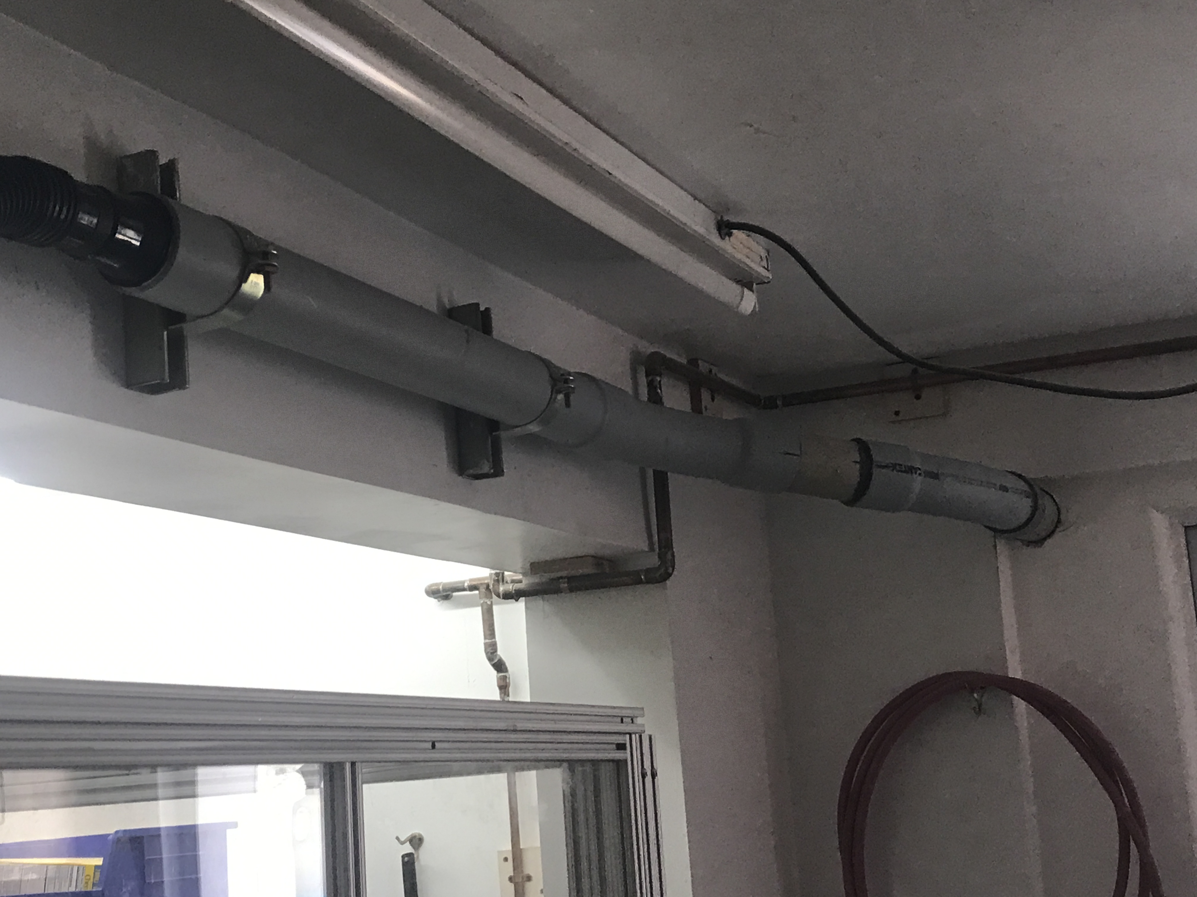
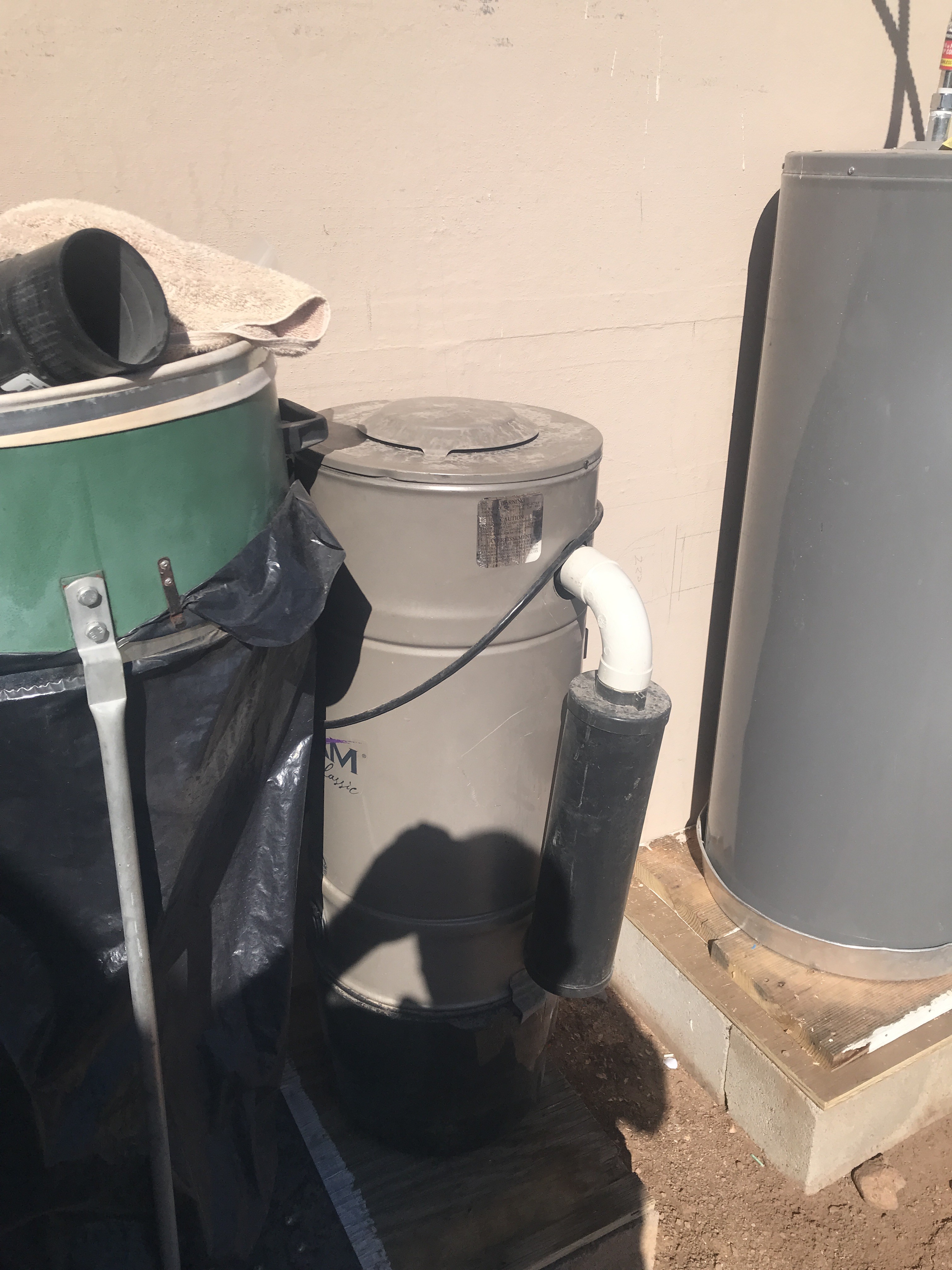
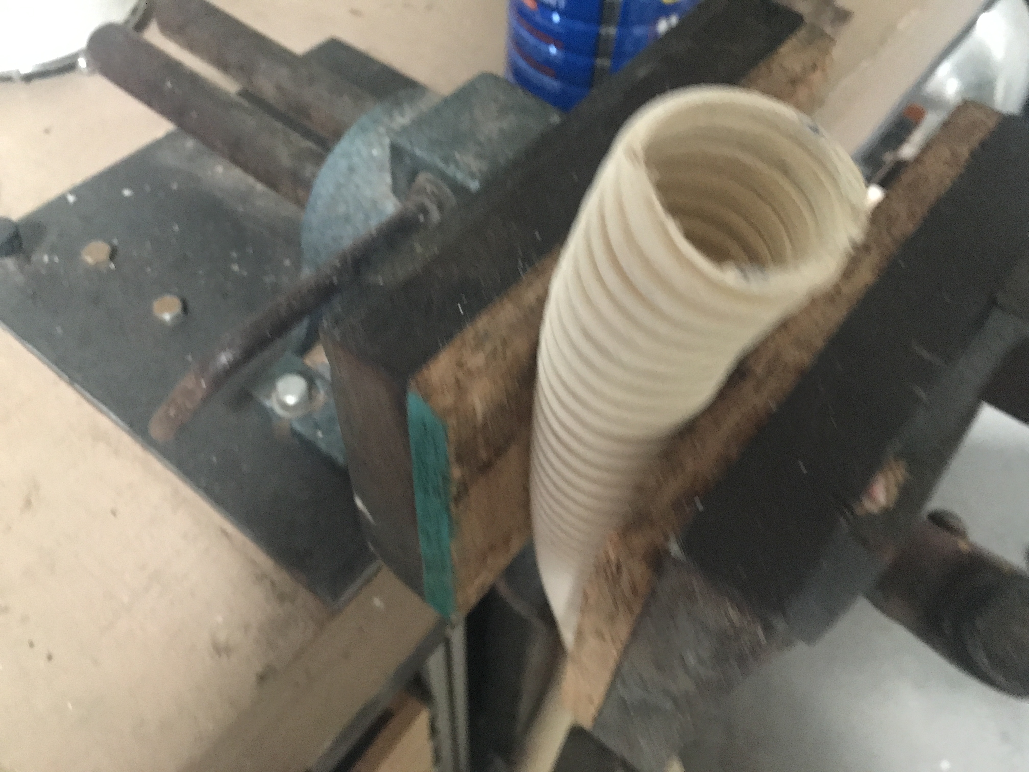
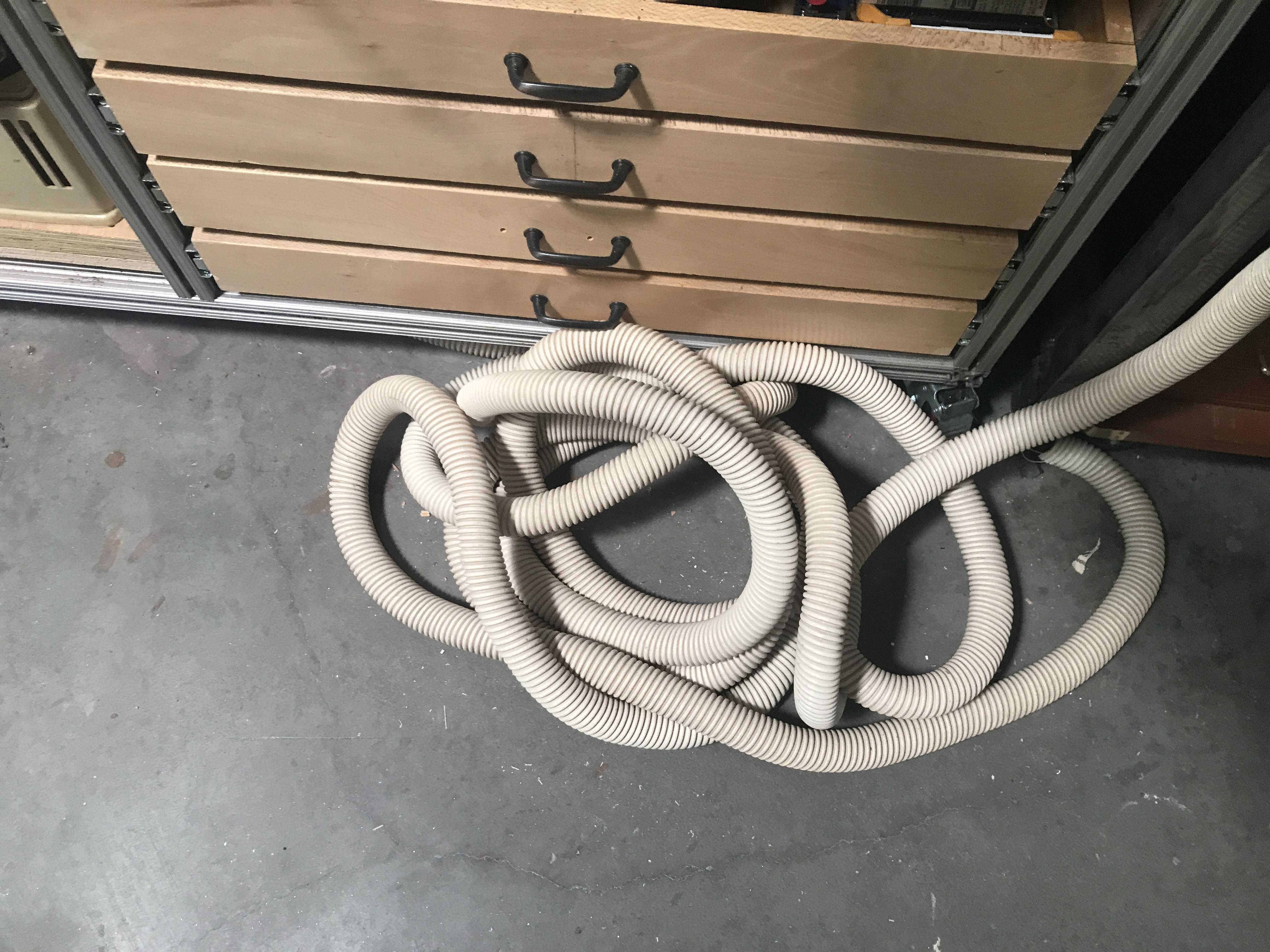
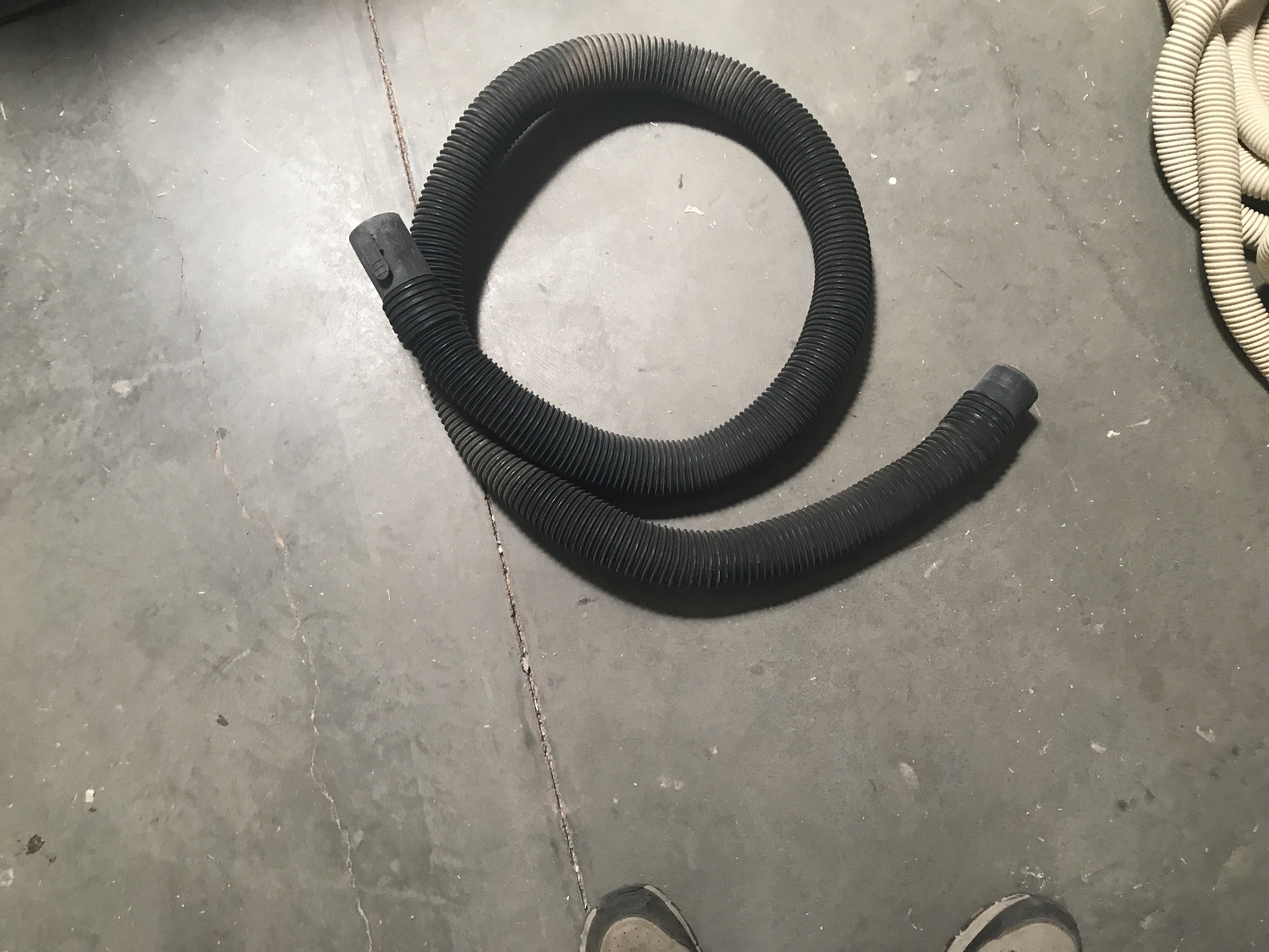
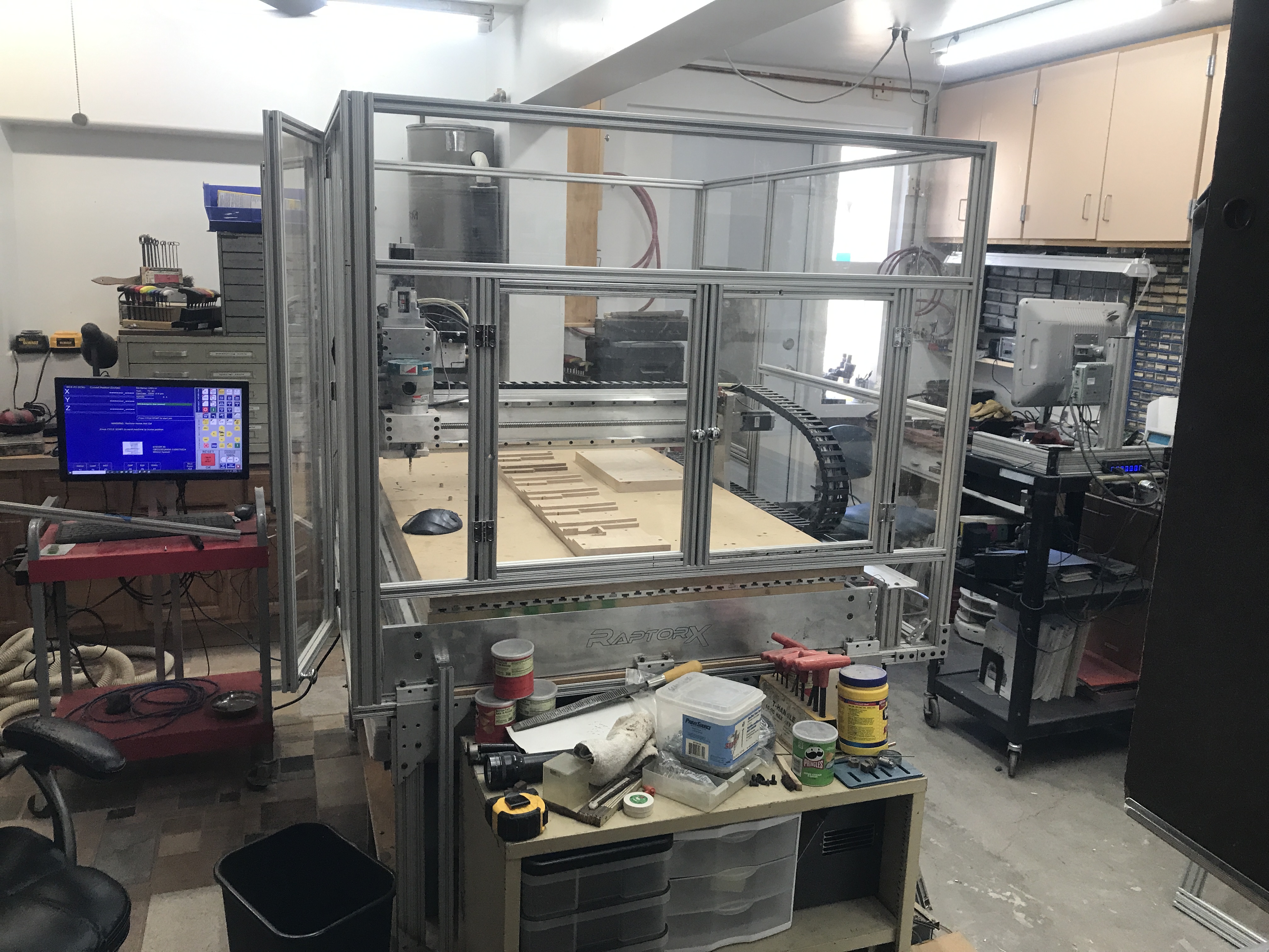
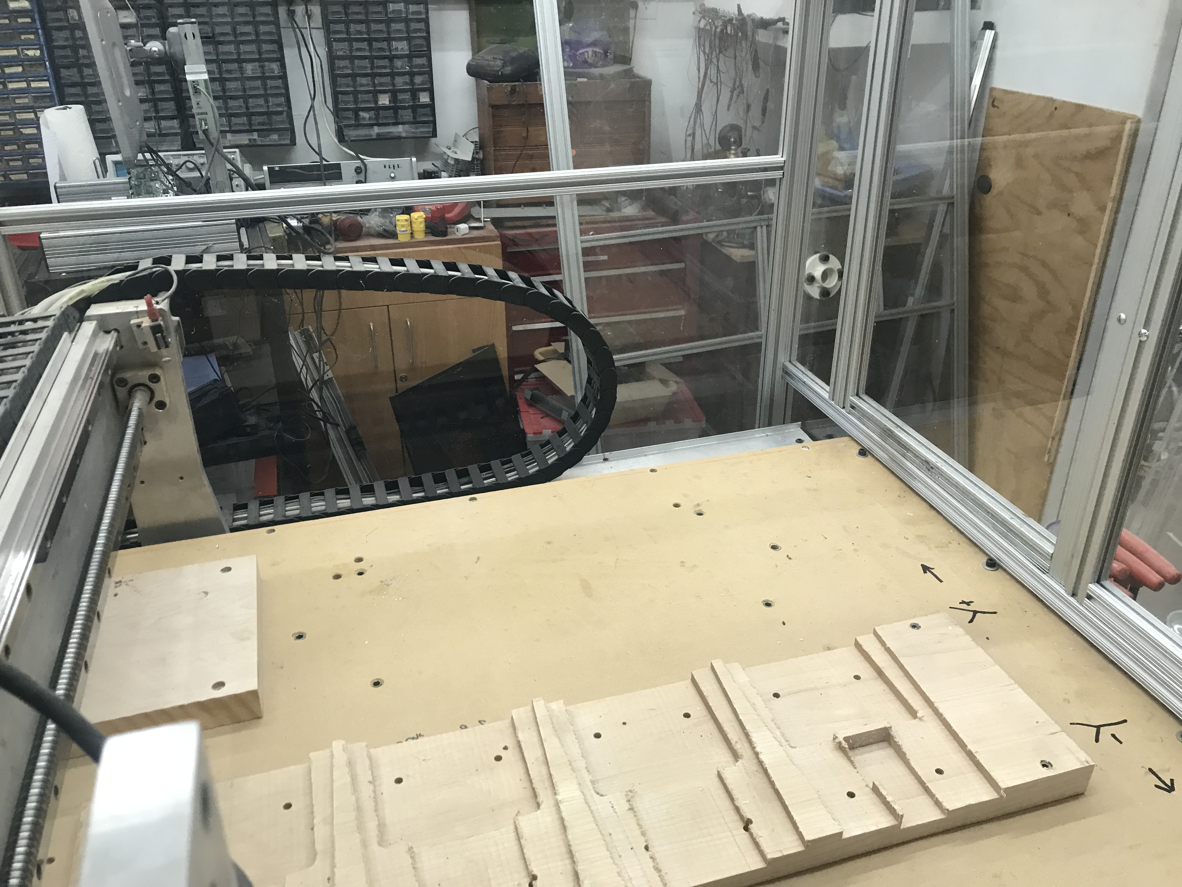
The cnc router is finally almost finished. The discharge piping is in and going outside to the dust collector. all the adapters are made for the inside of the cabinet and the piping inside of the building.
The noise was awful so I changed it out to large dust collector that I had setting around that is next to the house one. As with everything else none of the dust collector system matched up with the standard piping that is available at Home Depot. Adapters were printed out on my Bambu P2S 3D printer. The cabinet has been enlarged so now nothing hits the cabinet while I operate the cnc router.
I started designing the boot with a couple of test design pieces, I was able to make change the design to allow for proper magnet placement and fit the router perfectly. This is the new design.
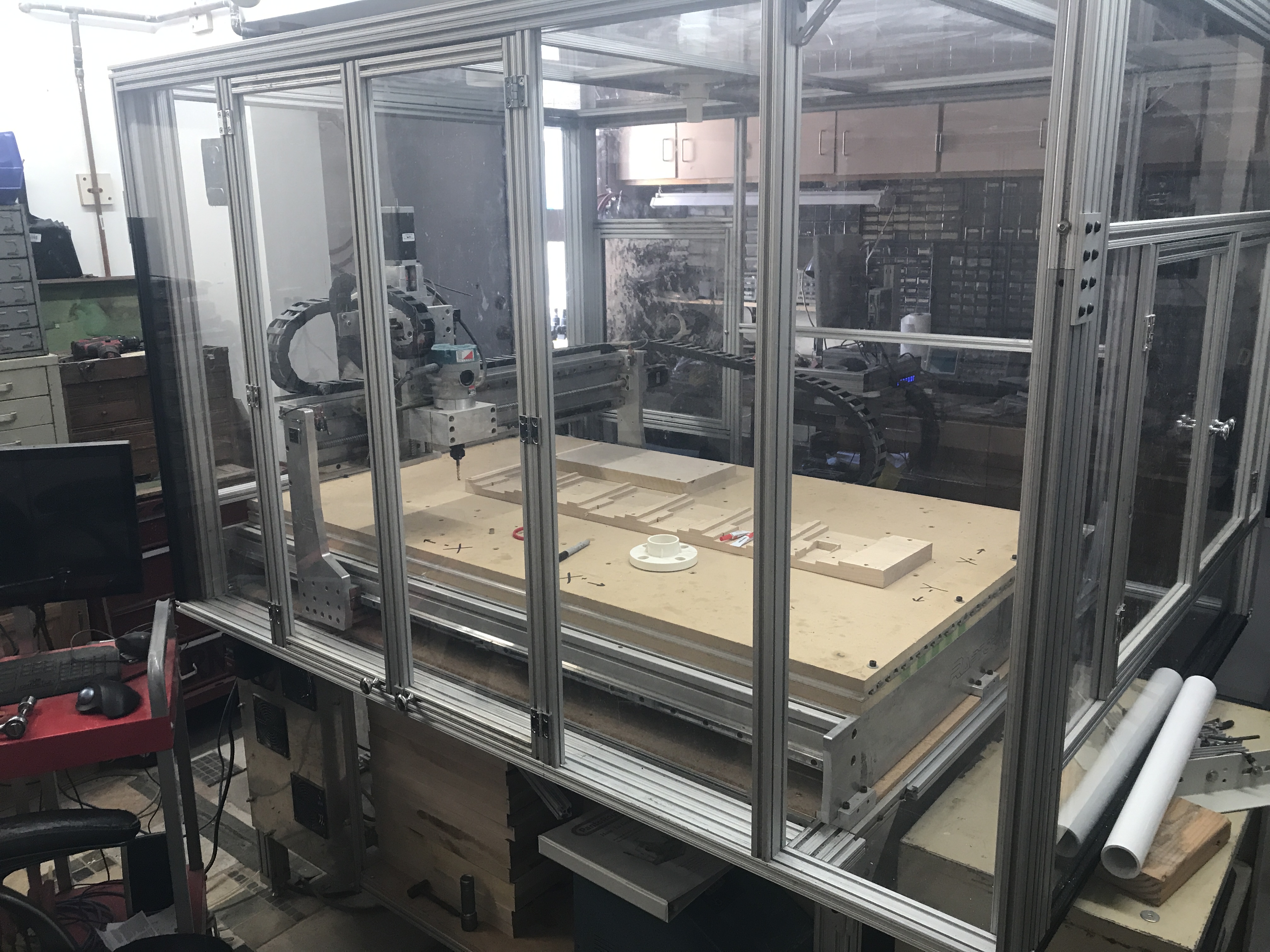
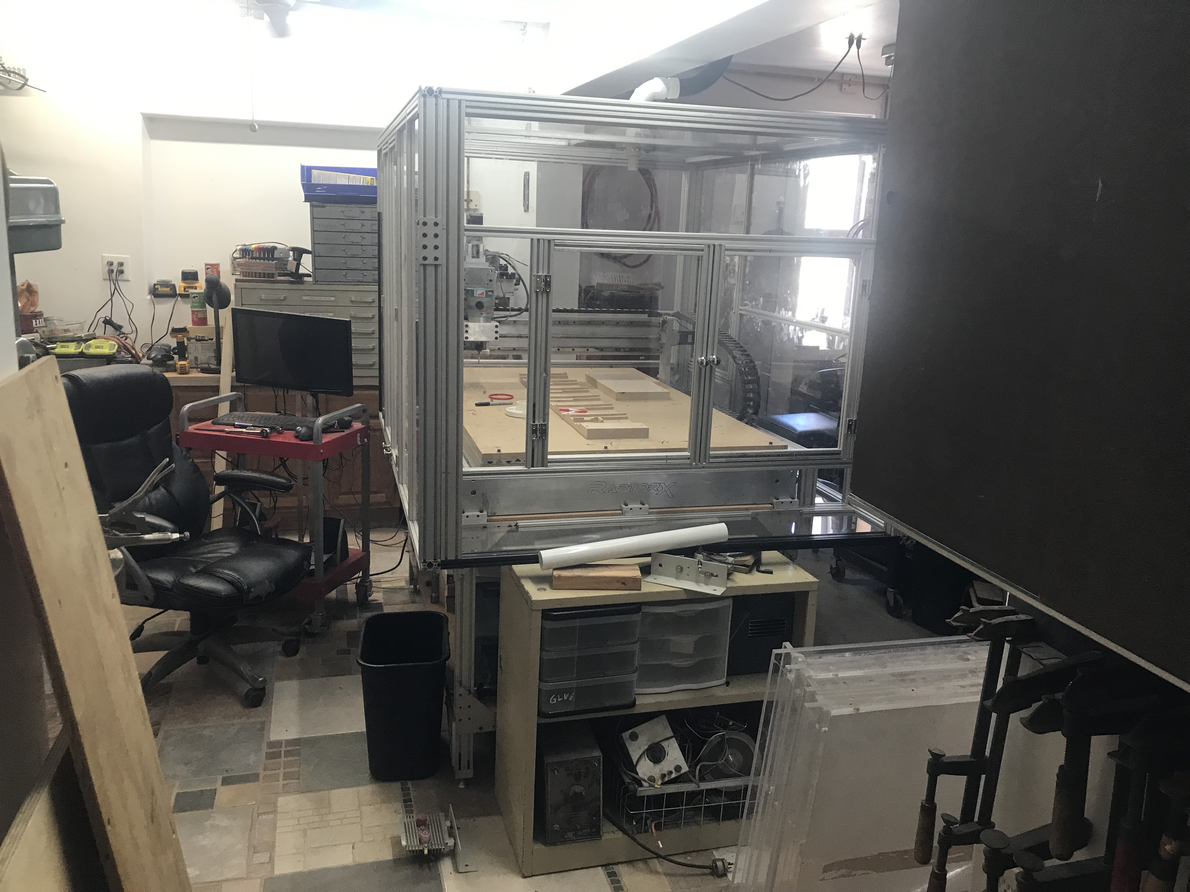
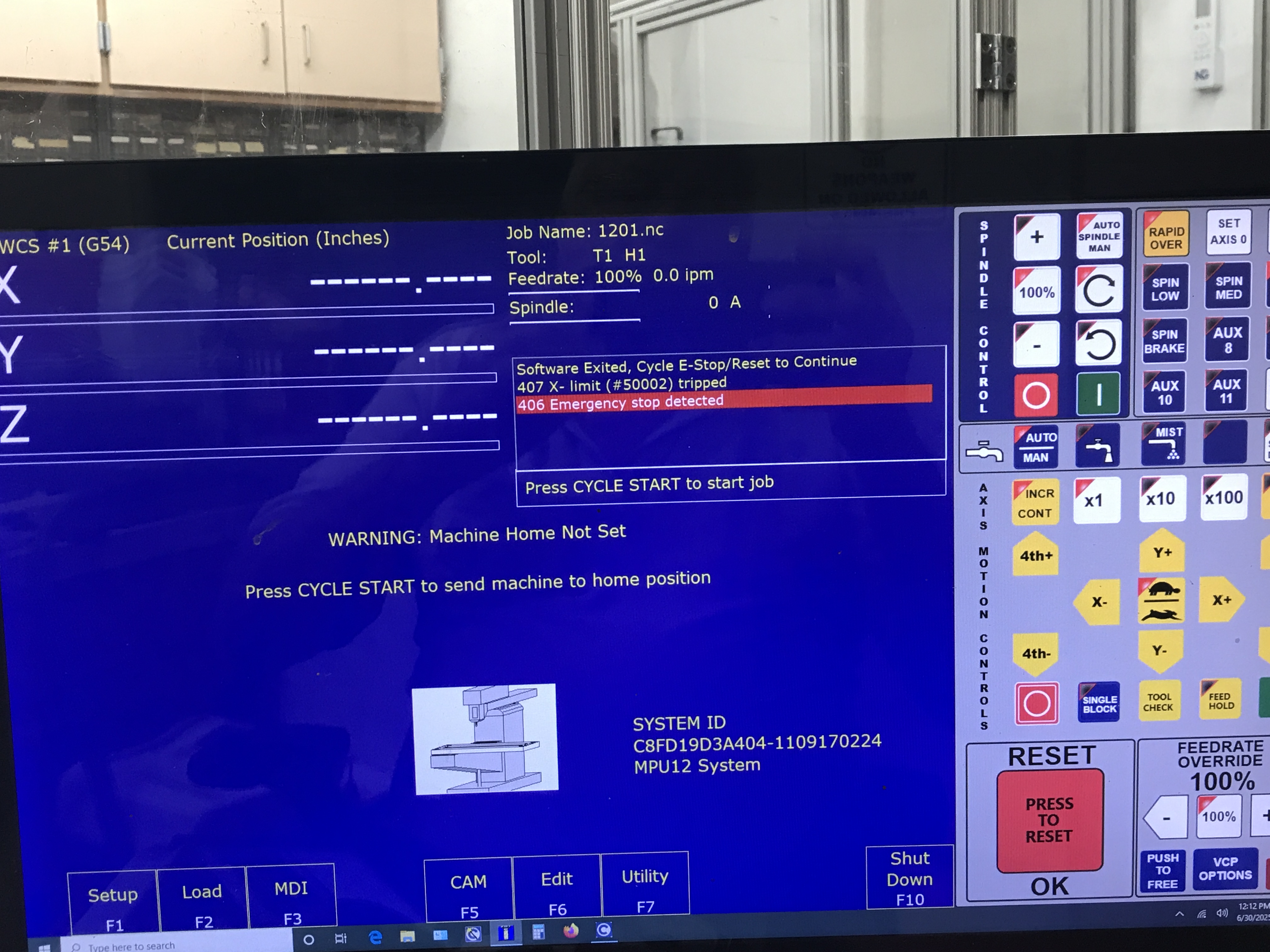
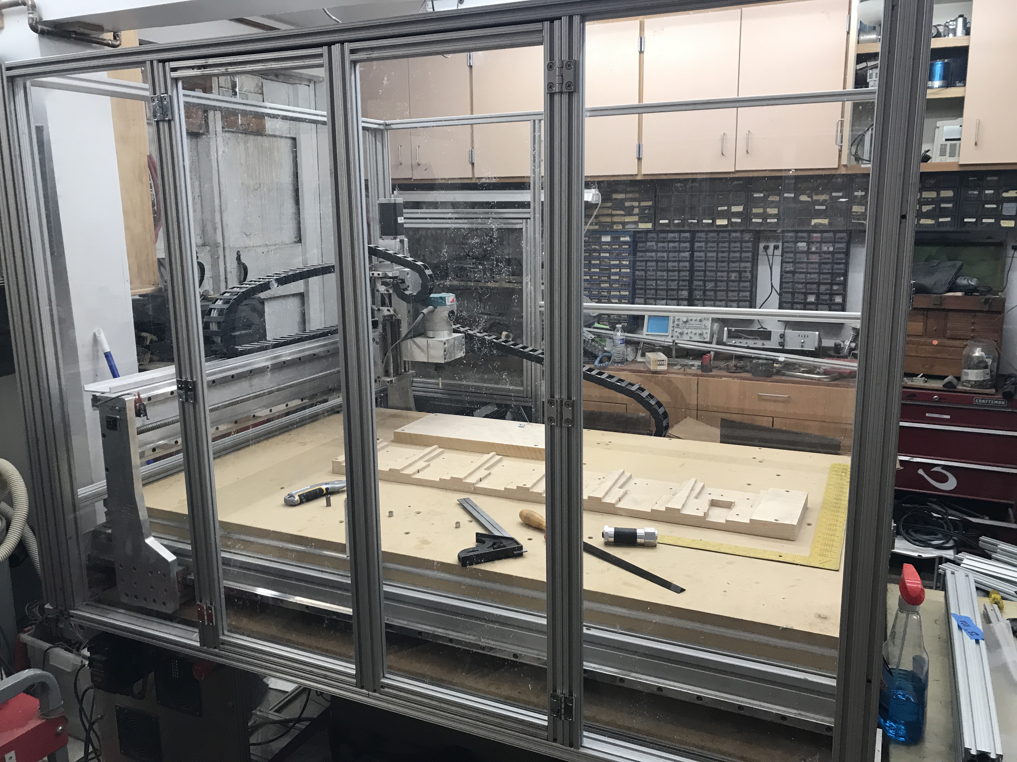
Getting closer to finally getting the cnc router back on line. This is a saga of the CNC router. The router was built here in the shop and it was used to make the stock and handguards for the VG1-5. 5 years ago I was running a batch of parts and hit an over travel stop. When this happen I just shut off the machine as something had come up and I could not finish the parts run. When I got bad to working on the router I could not get the machine to do anything. I kept getting this alarm code.
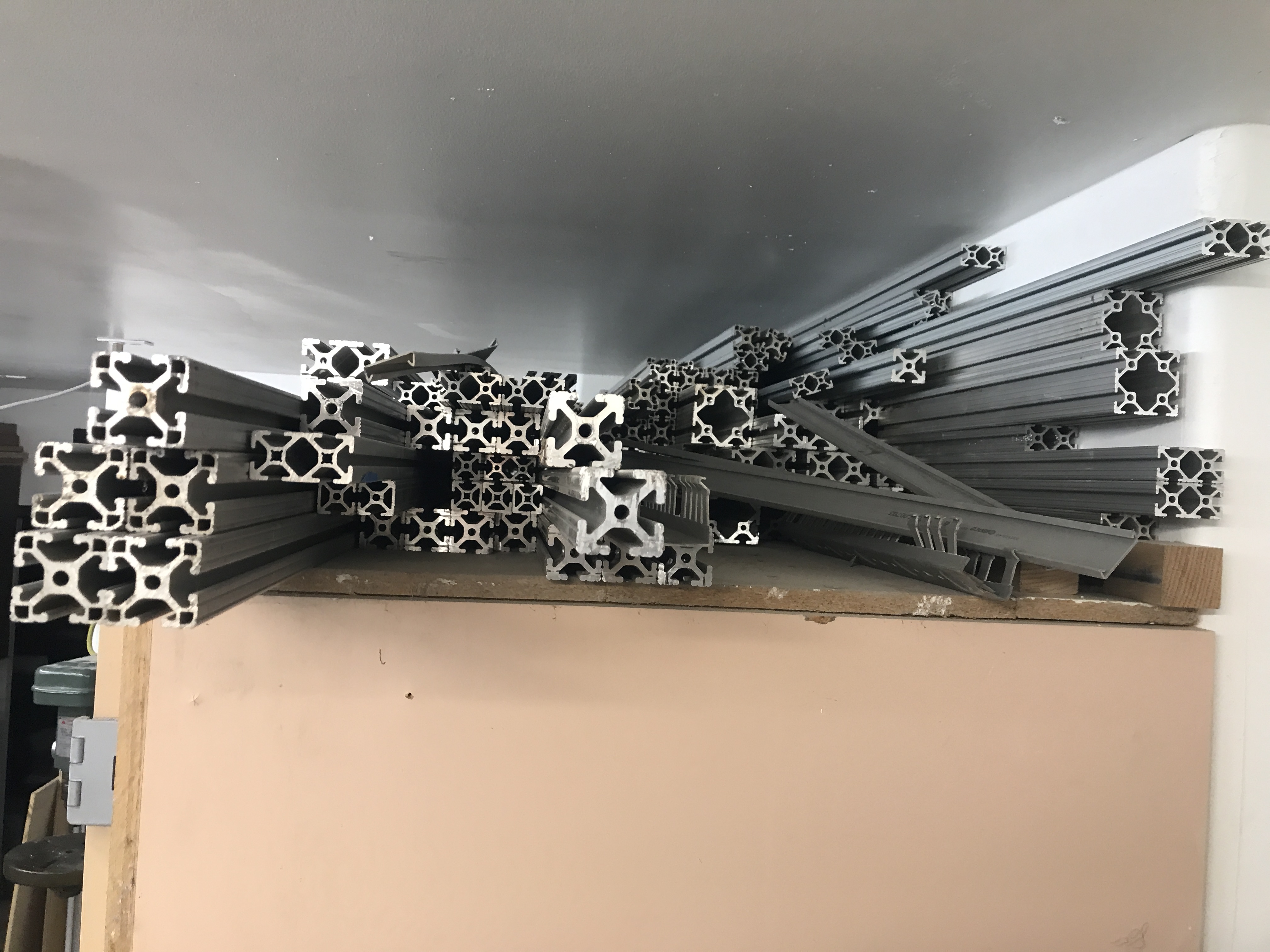
I did the build with 80-20aluminum extrusions and plexiglass. Both of these I had from recycle and demo jobs.
The big mistake came when I started to operate the machine and realized that I made the cabinet to small.
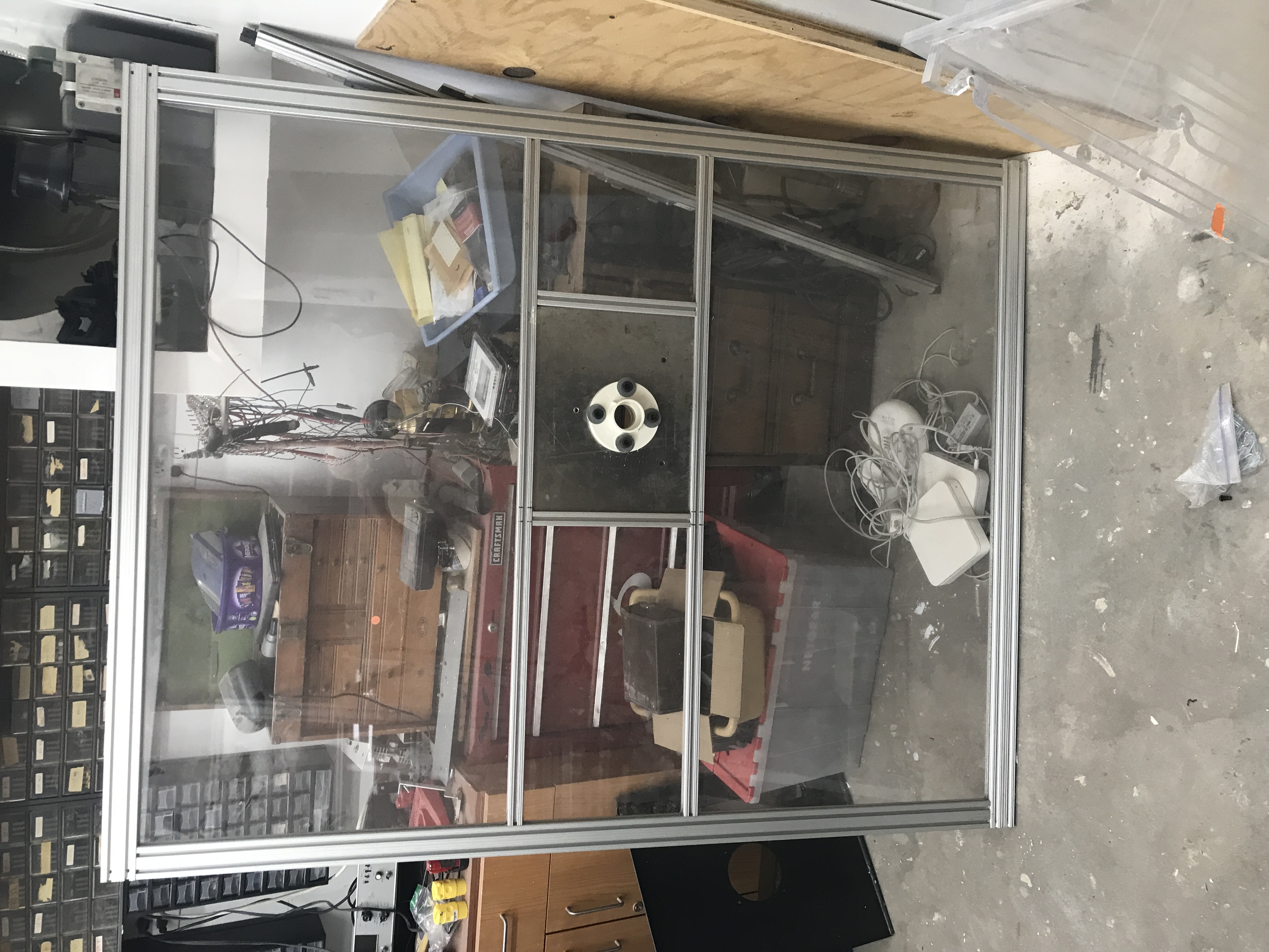
The time has come for me to re-build the cabinet. 2″ in the Yaxis and 7″ longer in the X axis. Some days you just wake up on the wrong side of the table. Back to the design board and fix it to allow me to go back to using it. I have reverse engineered most the lower receiver in Fusion 360 and will print the first model this week. This is the first print so I can test my solid model. Using the Bambu P2S printer I will print a 3D model. There are a number of modifications that will needed to be made, but I can check my initial model.
The issues that I have found deal with the measurements and using photos that were not an exact 90 degrees. Not comes the fun part of making minor changes to correct the issues. With the last test model machined I started putting the lower together and a number of issues were noted. The receiver dimension is correct for the holes, magazine release, magazine well and overall length and width. the magazine button and release lever are not deep enough. These are the noted problems. The first one is a very slight radius issue on the rear of the receiver just prior to the buffer tube
And you can see it is missing on my test receiver.
The 4th op is to thread the rear of the receiver for the buffer tub and to drill the hole for the rear take down detent pin and spring and the stock alignment hole. The holes were first cut to the proper size then a thread mill with the proper pitch. threaded the correct number of threads with the proper pitch. To accomplish this step a fixture plate was design and machined.
While doing research on the 1917 trench carbine I came across a rifle that I have never seen or even heard of. The V9000. There is a video on YouTube posted by LAI Publications. I just fell for this cute carbine. It also dissembles and the stock comes off.
My favorite magazine for my Broomhandle projects is the Finnish M/20 smg magazine. They are available at Apex gun parts.
The first step was to design the lower receiver to use a M/20 magazine. I started this process with using a cut Chinese Schnellfeuer lower.
With the new Bambu P2S printer here I decided to start printing out some of the components of the 1917 trench carbine to verify the design and measurements. The first part that I printed out and checked is the fire control group. After it was printed out it was checked with actual components to verify proper fit up.
|
||
|
Copyright © 2026 GunLab (KnownHost) - All Rights Reserved Powered by WordPress & Atahualpa |
||