I own a Hotchkiss portative machine gun and with it now fully operational it has become one of my favorites to take to the shoot.

My biggest complaint with it is that I just don’t like getting down into the dirt to shoot it. The butt stock is uncomfortable to use and the little tri-pod that came with it is really useless.


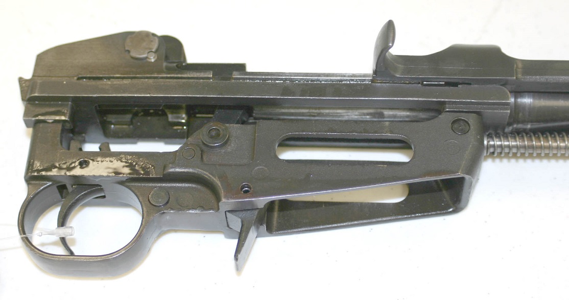
 A close up of the yoke.

On of my personal projects that I have been working on is designing a new tri-pod for it. I use to own a 1914 French Hotchkiss and let it go a number of years back, a mistake but we all do it. So I have taken four different paths in the design of a new tri-pod for my weapon. There is always the original British design for an adapter to a Vickers tri-pod.

 Actually this just looks like a great deal of work and really complex. The patterns to make the bronze castings would take a great deal of time to work out then the fixtures necessary to machine it would be numerous.
Then there is the idea of designing the patterns to cast a new yolk assembly based upon the Hotchkiss 1914 machine gun and the French 1907 St Etienne.


 This is a project I might tackle once the cnc router is up and running after the other major projects are completed.
The third idea is one that I found on the internet. It uses a yoke from a Hotchkiss portative and attaches it to a Vickers tri-pod. It is an interesting idea, but I really want something a little lighter and generally when I go to a shoot I usually bring my Vickers as well.
 So this leads us to the forth and final concept I am thinking of. This is using the concept of the Vickers-Maxium light machine gun tri-pod. It could be done by making an adapter to use the original yoke assembly and attaching it to a new column. The idea would be something like this.
 This yoke would be changed to use an original
 I would modify the legs so they would fold back against the sides.
 A rear basic traversing set up

 The elevation set up would have a handle to make it easier.
 It would not be done by the up coming shoot, but by the end of the year if I can find any time.