Categories

Library Thursday

This will be a quick post today. I just received my October firearms catalog from the James D. Julia auction site. All I can say is WOW. What an auction this will be.

Here is the link for the first lots auction.

http://jamesdjulia.com/auction/369-october-2014-firearms-auction/?session=1&utm_source=emailsub&utm_medium=email&utm_content=catonline&utm_campaign=gun_14_fall

Some of the items that I would love to have but is way beyond my means are:

Lot 1241 The Walther Volkspistol   http://jamesdjulia.com/item/1241-369/

Lot 1267 The Mauser 1906-08 flapper locked pistol   http://jamesdjulia.com/item/1267-369/

And one that I that is actually the top of my list is: Lot 1268 the 1917 Mauser trench carbine  http://jamesdjulia.com/item/1268-369/

So if anyone has any extra money that they don’t need I would really like the Mauser trench carbine.

Check out the catalog and look at the great stuff coming up.

Radom info Wednesday, 9-3

We finished the new knurling tool this last weekend and this is a post about the new tool. I have been using the Shars knurling tool for a while and was continuing to have problems with it so it was time for a change.

DSC_0010_sThe pivot pins are very loose which causes the tool to move when you don’t want it to and not move when you need it to. It was also hard to apply pressure the knurling heads with out using a pair of pliers. So a total redesign was necessary. This process was not with out a few problems. The first being that the computer crashed just after we did the design and had written the cam program. This caused a problem as we noticed a few items that needed a small dimensional change, but with out the original program that was all but impossible to accomplish. It was also difficult to machine the vise jaws with out the original drawings to match correctly with the parts that we had made.

DSC_0013_s
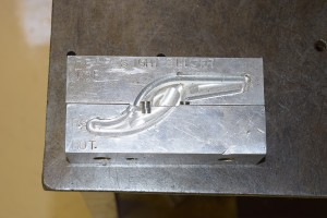
The was to make these parts would have been to machine the one side then put them in the new vise jaws and machine the other side to the proper shape and face cut the extra material off. Again with out the drawings I could not write a program to do this so we just face milled the other side off instead with out milling the actual shape in first. This lead to an interesting final pass.

IMG_2272_s

 IMG_2267_s

By the time we got to the final pass it was like cutting sheet metal that was a good 3/4 of an inch away from the vise. It worked but not a recommended practice.

Now that the two halves were made.

IMG_2282_s

IMG_2285_s
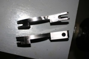
This one is a close up of the ends.

IMG_2284_sAnd one more put together.

IMG_2280_sWe needed to make the clamping screw. The first method was to silver braze and pin the screw to the pivoting block. That did not work so well.

DSC_0008_s_wNot enough solder and the side walls to thin. So the next attempt was to add a great deal more silver solder.

DSC_0009_s_w
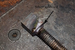
It also pulled out with the first attempt at using it. So the final method of attaching was tig welding.

DSC_0012_s_wIt not works like a champ and makes a very nice knurled on the VG1-5 front barrel support. The video on that will be coming up soon. Hope you enjoyed this update. Looking to hear you comments and ideas.

Shop Tuesday, Late 9-3-14

Sorry for the late update. It has been a little busy and now with school starting again I found myself out of time. The major update for shop Tuesday is the design work that has been accomplished on the barrel fluting machine. I spent most of last Saturday morning and almost all of Monday working of the design. Some major changes have been incorporated. As a brief intro here are the solid models that posted a while back.

flutting machine assembly_s

flutting machine2_s

flutting machine_sAS you can see the vise is bolted to a rotary flat plate. This flat plate then rides in an opening of another steel plate. The complete assembly was then bolted to a large plate and then assembled to the side of my forging press.

The changes that we are currently working on allow the lower assembly to move up and down. This change will allow for a greater range of work possibilities. We also changed the method for holding the chuck to the rotary table. This a basic look at the new design.

flutting machine_3_s

flutting machine_2

flutting machine_4

You will notice that we design the rotary table portion with 10 degree increments to allow accurate placement of the table in relation to the fluting tool. We also design a simple but effective tool holder. There is still more to do with the design, but I hope to have the design portion done this weekend and then start making it.

Hope you enjoyed the update. Comments and ideas are always welcome.


Weekend update

Most of Saturday morning was spent on another solid model. The actual projects that were accomplished were finishing the knurling tool and get back on the VG1-5 knurling project.

So first on the list is the knurling tool. I have one that I bought form Shars. I just did not like it. It moved to much and made me very nervous when I was using it up close to the chuck on my lathe. It would move when ever it wanted and most of the time not when I wanted it to. So my neighbor and I design one, wrote the programs for the Allen-Bradley and then finished it off this last week.

Here are a few pictures of the build process.

IMG_2272_s

IMG_2281_s


This after the jaw was machined and we put it in the web milling machine to cut off the back side. I have a complete post for later in this week.

Sunday was spent playing with my new Nikon 5300 series camera. I have also started a night class at the local college on digital photography. I did a basic video with a voice over to test its capability.

The rest of the time was spent with working out the design of the chamber fluting machine for the VG1-5 and other barrels.

flutting machine_3_sThe design is in it final stages and I will post on this tomorrow.


Sunday Answer

The part from what is it Saturday is: The lever for a lever delayed blow back San Cristobal. IMG_0251_sThis is the basic function of the part. It is design to keep the bolt closed against the barrel until the pressure drops enough to allow safe operation. Here is a series of pictures showing this is operation.

As the rifle is fired the bolt is closed up against the barrel and held there with spring pressure.

IMG_2441_s


You will notice that the tab on the bottom of the lever is pushed down into the receiver.

IMG_2441_sarrow

This is what just the bolt looks like in that condition.

IMG_2447_sAs the round is fired and pressure is placed upon the bolt it tries to move backward. This causes the bolt to try and move backwards. The lever keeps the front of the bolt closed and starts moving the rear of the bolt against spring pressure.

IMG_2442_s_wordsAnother picture of the bolt by itself showing what is happening.

IMG_2448_sOnce the bolt is totally open the lever is no longer having any effect and the bolt can now open allowing the cartridge to eject.

IMG_2445_s

IMG_2446_sThis is a picture of the bolt during this phase of operation.

IMG_2449_sThe last picture if with the lever removed form the bolt.

IMG_2451_sThanks for coming by and your comments and opinions are appreciated.

What is it Saturday

Once again it is time for what is it Saturday. Enjoy and guess away.

IMG_0251_sHere are a couple of additional views.IMG_0259_s

IMG_0258_s

Friday video

Earlier this week we posted about the FG-42 first model bi-pod leg male stamping die. This is a video of us making the die.


This is a picture of the final die.

SAM_0025_sHope you enjoyed the video. I appreciate all comments and suggestions to improve the video and the content. Thanks for watching.

Library Thursday

First off you can see that we changed the title for the Thursday post from book review to library. This was done because I wanted to add more then just book reviews. I wanted to add information to the Gun Lab library that I thought would be useful to you.

So this first post is from a friend of mine that wants to remain anonymous. So for this post we just call him Joe. Joe had the opportunity to have every piece of brass test that he had that was attached to a weapon. This included Maxim guns, Nordenfelt weapons, Gardner guns and any thing else he could find. This is that report. I found it interesting and very useful. I hope you do to.

Bronze Composition Analysis document

Random Info Wednesday

To proceed with the building of the VG1-5 we needed to design and build a barrel chamber fluting machine. With the number of barrels that we need to make to complete the project I needed something that is accurate constantly, has repeatable, is semi automatic in operation and can be used for other rifle projects. This has lead to a variety of different concepts and we are now starting a solid model of the machine. Some of the problems that we have had to work through are how to accurately press in the flutes for the proper depths consistently,  how to hold the barrel accurately and in alignment with the fluting tool, and how to hold the barrel so I can flute and remove the tool with out pulling the barrel out of the fixture. We have solved a few of the problems and still have more to deal with. This is the solid model that I have developed so far. the first set of pictures shows the base assembly using a 6″ lathe chuck.flutting machine2_s

flutting machine_s

This next photo shows the basic assembly.

flutting machine assembly_sStill working on the control method. I would like to put control switches in as well as a DRO. I will be working on that design this weekend. Your comments, ideas and opions are welcome.

Shop Tuesday

We posted about the female die for the FG-42 first model bi-pod stamping die a while back. Today’s post is about the male stamping die. This first set of pictures is the solid model for the male die.

male die 2_s

male die 1_s


Once again a few pictures to give you an idea of what the bi-pod should look like.

IMG_2318_s

IMG_2317_s

IMG_2316_sWE are also trying something new with this post and that is provide a video of the master cam program as it operates.


Here is the video of the master cam program:

I am working on an audio track for the next posts, just did not have any luck on this one.

The total run time to make the die plate is 4 hours. tool costs $210.00, total time for for solid modeling, master cam programing,tool set up is 16 hours. Material costs is $60.oo. Just to make the die the cost was approx $1550.00. dividing this cost over 300 pieces brings the basic cost for this die down to 5.00 per piece for this die. There will probably be 6 sets of dies per bi-pod leg.

Friday hope to have the video of the die being made. Stay tuned and comments and suggestions are always welcome.