Categories

Changes to Gun Lab

I have decided to make a few changes to the way gun lab works. I personally can watch machining videos and look at solid models and guns all day. I guess that is because it is what I enjoy. I mean I take my vacations to go to factories to watch things being made Plastic factories, pottery factories, machine shops, museums to look at weapons and my wife goes along with me. However, I understand that most people want to see other things as well. So here are a list of the changes that I would like to make to the site.

Weekend followup Monday

Monday will be for an update of what went on during the weekend. A basic run down of everything that happen in or around  the shop. This is to give an idea of everything that has to go on to keep things running.

Shop Tuesday

Tuesday will be for showing the part that has been made.  The solid model that was worked on or the program that was written. Anything that went into making the parts that we make.

Random info Wednesday

Wednesday will be for information that we have come across that would help. Where we buy material, people and companies who have helped us,  new products, videos that we find dealing with gun or parts making. I want to do a segment on people that are in the  industry.  Anything that I feel like taking about. Classes that we are taking, talking about the shop equipment that we have and use. Talking about firearms that we are interested in making in the future, general discussions on manufacturing or weapons, interviews when possible.

Book review Thursday.

There a large number of books in the reference library here at gun lab. Machining books, gun books, manufacturing books, information that is helpful in every aspect of what we do. I want to do a basic run down of the book and where to obtain it. In some cases a sales commission is give if you buy the book through our link. All money from this will be donated to the wounded warrior project. Having served in the military and coming from a family of military people I feel strongly toward this cause. I hope that you do too.

Video Friday

This will be the day that I post videos of the parts or equipment that we have made.

Guess this part Saturday

I have a 40′ container of misc parts. Saturday will be for taking pictures of parts so you can test your knowledge of small arms.

Answer Sunday

This will be the follow up day that answers  Saturday’s  question.

I want to add a library to the site dealing with information pertaining to gun lab.

Please feel free to comment about the changes and any recommendations that you have. We are looking to involve our viewers to improve gun lab to become the best site possible.
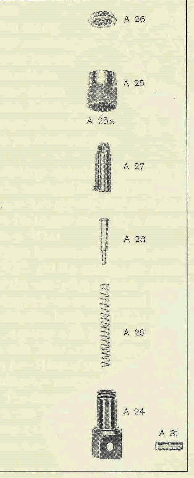
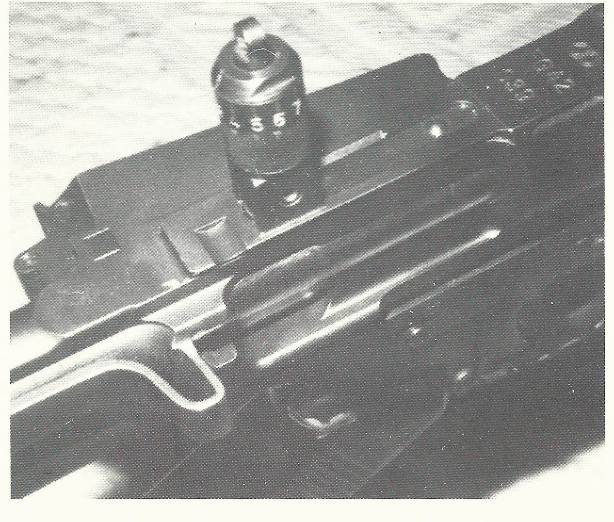
FG-42 first model rear sight button

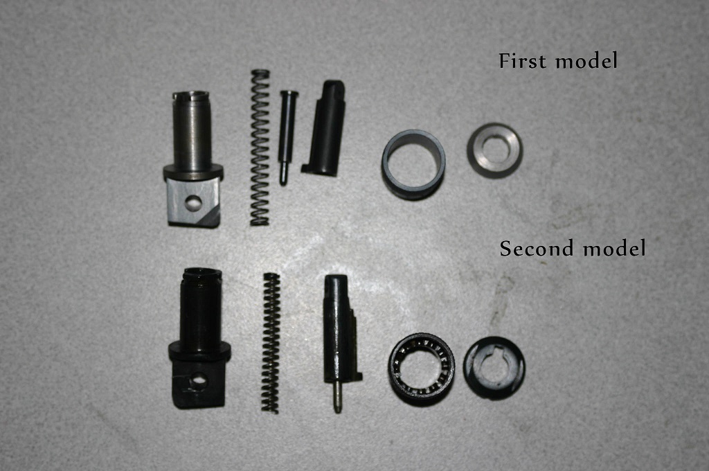
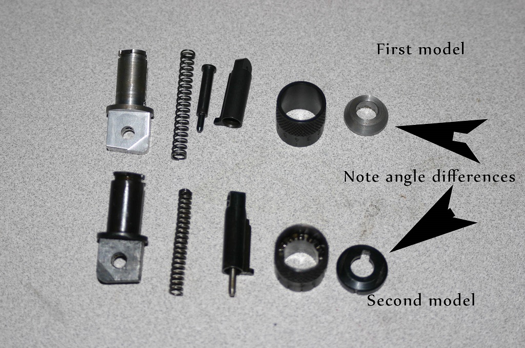
This post is about making the rear sight button for the FG-42 first model. To give you an idea of the complexity of this part I am adding a picture from “Death From Above” . This is a component break down of the parts for the first model FG-42 rear sight.

FG-42 rear sight compoment parts2

There is also a picture of it installed on the rifle.

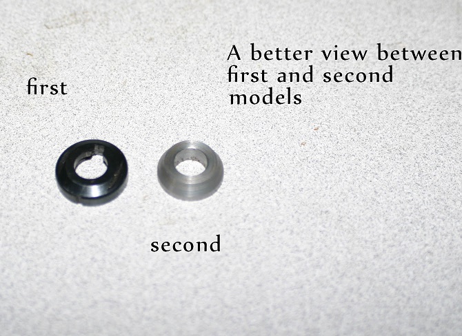
FG-42 rear sight first modelThe important information on these pictures is the angle of the button that holds it together and the design of the sight post. This post is about the lathe operation for part A 26. This is the button that holds the entire sight together. If you compare this sight with a later model Fg-42 you will notice the differences in the angle and the thickness of the part. The internals however are inter changeable.

IMG_2370_w_s

With the part we are making in this post we are dealing with the button that holds it together.

IMG_2372_w_sThis picture will give you a slightly different view.

IMG_2373_w_s


Now that we have finished the lathe op for this part we will start designing the tools and fixture necessary to complete the mill operations.

Video on finishing machining the FG-42 rear sight base

In the last video concerning the FG-42 rear sight base we showed you the lathe work required to complete the first op. This video will show you the rest of the work required to complete the rear sight base on the machining center.

Again just a reminder of the part we are making is solid model form.

FG42-A24 1_sIn this video we will take it from a turned part.

IMG_2299_sTo a final part ready for assembly.

IMG_2310_sSo Lets start.


The total milling time for this part is 10 minutes. Hope you enjoyed the video.

Update on work around Gun Lab.

Not everything is fun and games around here. There is always maintenance to accomplish as well building projects not related to guns to perform. This Sunday was one of those days. My boss, wife, deemed that the doors needed painting as well as the door frames. So all the doors except the big steel doors at the shot were painted. That is a total of 14 doors and frames that were painted ( house, guest house,shops and metal storage room) as well a new insulation cover built and painted for the walk in cooler I built.

IMG_2340_s

IMG_2341_s

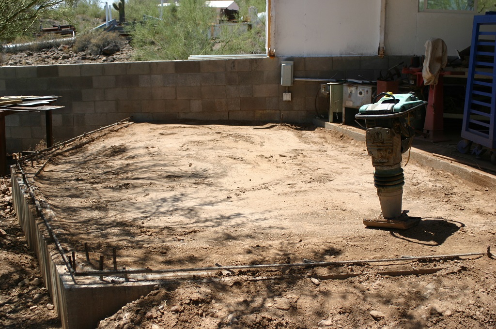
In addition a friend dropped of his wacker  to compact the soil for the addition at the fab shop. At my age I am just to old to play with this stuff, but I did it any way. The good news is that task is complete the bad news is that I feel it, big time.

IMG_2325_s

IMG_2323_sHowever with the compacting completed finished I am ready for the next task.

IMG_2336_sIt was also time to clean up the fab shop. It has gotten a little out of order and impossible to work in.

IMG_2327_s

IMG_2330s

IMG_2331_sSo a major clean up was in order. My better half and I finished it late Sunday. What a job.IMG_2339_sNext I finished installing the lights I had on hand and wired them up and installed light bulbs.

IMG_2338_sThe excitement was that hootie showed back up and stayed around for a few glamor shots.

IMG_2333_s

IMG_2334_sHe is great for dealing with the mouse problem. That’s all for this Sunday and I am already back at work on gun stuff.

Need a Little Help

I have finished the lower receiver for the Sudanese AR-10. I would now like to make some of the other parts for it and the Portuguese AR-10. I am really looking for Drawings and parts. If anyone could help it would be greatly appreciated.

More updates on the Sudanese AR-10

We have finally finished the solid model of the Sudanese lower receiver. The total time that has been spent making the solid model is 60 hours. Considering that there were no engineering drawings that were readable and the receiver we had to work with is cut up, I do not feel that is was excessive. We are still working on the tool list , programing and fixtures that are necessary to make it, that will be in the next post. The material for two test receivers is here and we are working toward the next phase.

So here are the solid model updates. We have gone through an corrected some of the radius on the inside and out side of the receiver.ar-10 receiver drawing4_s

ar-10 receiver drawing1_sWith the final model they blend better and look like the original rifle.

We have also started the lettering on the side of the receiver.

ar-10 receiver letters_sThe next update was to add the logo we are going to use on our receivers. Being that Armalite is copyrighted as is AR-10 we had to made a few changed as you can see. this is an original rifle.

0A1A1ARM-036026_4

This is our version.


ar-10 receiver drawing2_sThe full auto trip sear was removed from the model and stops for the selector were added.

ar-10 receiver drawing4_sThe original Sudanese selector was different the all the rest.

selector 1Which means that we going to now have to change that as well.


ar-10 receiver drawing11_s

The changes have been made and the lower receiver should be correct. Comments are appreciated.

Machining the FG-42 bi-pod leg female stamping die

This post is about machining the stamping die for the bi-pod leg on a first model FG-42. This will be the third stamping die out of a set of 5 dies. It is also one of the more complex of the dies in the set. I will start with the solid model that was drawn up in solid works after being scanned.

Bi-pod_s

Bi-pod1_s

Here are a few pictures of an original bi-pod legIMG_2317_s

IMG_2316_s

IMG_2318_s


Here are a few still pictures of the female die.

IMG_2313_s

IMG_2311_s

To give you an idea of the time required to do this die it took a week of design time to take the 3-d scans and convert them into usable solid models. It took another day to write the master cam program. The total time to set up the machine and run the die 5 hours. The material cost was $ 65.00. Tooling cost was $120.00.

We are working on the matching male die and will have a post about that soon. Hope you enjoyed the video and understand the time required to complete a project

FG-42 rear sight base machining video

I posted the still pictures a little while back on making this part. Here is the lathe video on machining the first op.

Just as a quick refresher on the part being made, this is the solid model of the part.

FG42-A24 1_s

FG42-A24_s


After the first op, which is the lathe op, this is what the part looks like.

IMG_2299_s

IMG_2300_s

I hope you enjoyed the video.

FG-42 first model rear sight

We have been working on the rear sight for the FG-42 first model. The first picture that is a solid model of the entire sight assembly.

rear Sight Assem_sThe next picture is a picture of the component parts.

rear sight assem explode_sThe part we are currently working on is the base of the sight.

FG42-A24 1_s

FG42-A24_sSo now that you have seen the solid model it is now time to show you what the actual machined parts look like and the process that it takes to do it. The first step is to run it on the lathe.

IMG_2278_sAfter that there is 5 ops to complete the part.

IMG_2292_s

IMG_2293_s

so now back to step one on the lathe.

IMG_2299_sNot only is it turned but also drilled the the proper size on the inside.

IMG_2300_sThe next step(op 2) is to cut the flats on the side of the base.

IMG_2302_sThen op 3 cuts the notches on the other end.

IMG_2304_sanother picture from a slightly different angle.

IMG_2305_sWith op 4 we cut the grove that allows the sight to slide up and down.

IMG_2306_sAnother view.IMG_2307_sThen the pivot hole is drilled and a slight bevel is cut into one side.

IMG_2308_sA better shot of the bevel.

IMG_2309_sThe last and final op is to cut the bevel on the opposite side.

IMG_2310_sThis is the first set to be cut.

To give you an idea of the time and money necessary to complete this one small part. The time to solid model this part from the 3-D scans was a couple of hours,time to write the lathe and mill programs and set up the machines was approximately 8 hours. Material cost was 60.00.  Run time on the lathe is 5 minutes per piece and run time on the mill is 10 minutes for a total run time on this part at 100 hours. Tooling costs is 200.00. This  makes a cost to make this one small part approximately 25.00 each.

I will have a video on making this part in the next week. Thanks for staying tuned in.

AR-10 Sudanese contract

A while back a close friend of mine brought over a parts kit for a Sudanese AR-10. There are no receivers available for this rifle anywhere. However, he did have a cut up receiver. In-addition another friend had sent be some drawings that had been photocopied so many time that done of the dimensions could be read. The real excitement is that I have always wanted an early style AR-10. So while I was waiting for material, tooling or fixtures to be made for the current projects I started another project. that is to design the solid model of the lower receiver. This is that story.
The first thing that was accomplished was to made large prints from the files that were sent of the lower receiver.

5y5dgl

Once I had that I started adding dimensions based upon measurement of the cut up one.

IMG_2257_s

You can see the measurement in red on the drawing.

This is the start of the solid model, day one in the process.

IMG_2258_sc

The following pictures are the progression of solid modelling the receiver. Keep in mind that this project was only worked on on weekends after we shut down the machines or in the evenings.
A few more pictures of the work after the first day.
ar-10 receiver drawing_s

ar-10 receiver drawing 2nd_s

This is the model after the second session at the computer.

ar-10 receiver drawing2_s
ar-10 receiver drawing3_s

ar-10 receiver drawing4_s

And again after the third opportunity I had to work on it.

ar-10 receiver drawing7_s

ar-10 receiver drawing6_s

This is after the forth session.

ar-10 receiver drawing9_s

ar-10 receiver drawing8_s

And a cut away of it to show inside dimensions.

ar-10 receiver drawing cut away_sThis last set of pictures is the final version.

ar-10 receiver drawing_s

AR-10 HIGHREZ_s

I will be going over every radius, angle,hole and dimension again this weekend to verify that everything is correct with this solid model. I will also be making the changes to make this a semi auto receiver only.  The tool list has been generated and I hope to be working on the fixtures and programs soon. Let me know what you think.