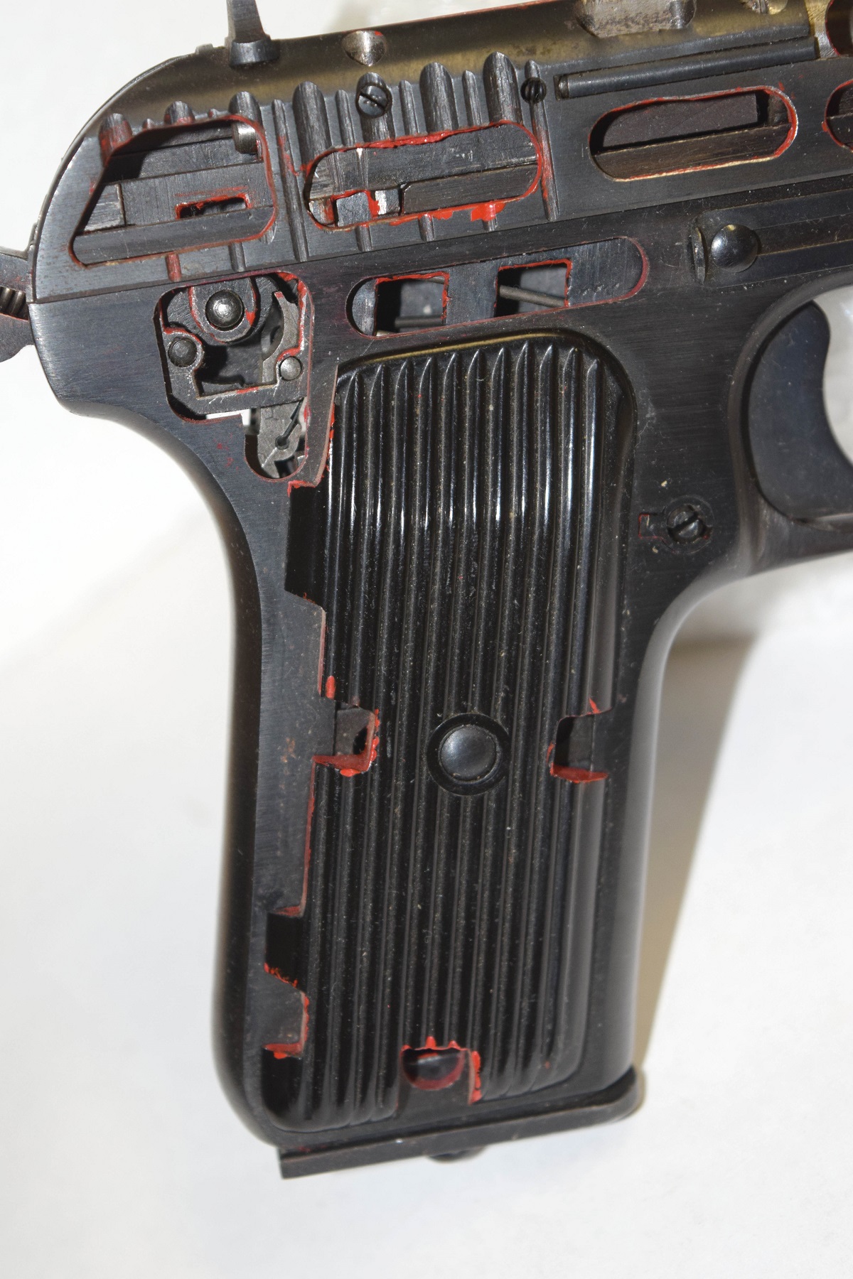
Another hard one, but it is a gun part.

|
Another hard one, but it is a gun part.
Here are two pictures of a Lowell gun. It came out during the time of the Gatling, Nordenfelt and Gardener gun but at the very end of that time period. Only a few were ever made and I was lucky to photograph this one before the museum closed.
From the days of 35mm photography. In this post we are going to look at making a magazine. In this case a 22lr pistol magazine. This magazine was stamped out on a progressive stamping die. In a machine that would look like this.
So lets take a look at the steps that would be required to make a magazine. Starting from a role of steel metal to the final product. The sheet steel is removed from its coil and fed into the stamping machine. The process start with the initial cut and a pilot hole or holes that serves as a locator hole for following steps in the process.
First step. Initial cut of the magazine and two pilot hole for locating the sheet metal for the next step.
Last Sunday was a much easier day. It was a large amount of fixing things as well as shop work. The A/C went out in the house so testing was conducted and it was found that the evaporator fan went out. Time was spent on removing it to get a replacement today. Then the bad luck just continued. Both a/c’s went out in the machine shop and had to be repaired. I finished the electrical to the spot welder and got them running.
I made bottoms for the library index card cabinets so they are now being used from odd parts, like the barrel for an Astra 400 or the bolt from a Winchester 73 bolt and feed ramp, any parts that did not require a large cabinet to store them in. We fixed a problem with the table saw and then cut a 3/4 mdf board for the cnc router.
All the firing pins for the VG1-5, the Star pistol and the M1930 Sauer have been sent to heat treat. The buffer pins are there as well. The spot welder have been wired up and the coolant system will be finished this weekend. The first rifle was sent a while ago to Greg who took it to the first testing facility for ATFE approval. The second one will be out when the parts come back from heat treat. We will be spot welding the receivers together soon and all the material for the bolts is here and going on the lathe for the first op in the near future. My work load has dropped of a little which helps and I hope to be back making regular posts soon. This weekend is full of mandatory maintenance projects to get the shop back in order. That is all for now. I went to do a little shooting on a few weapons in my collection that I have never fired only to find out that the firing pins were broken. In this case the pistol that I had taken out was a Sauer model 1930 32acp pistol. For some odd reason I happen to have three of these cute little pistols and two of them had broken firing pins. Now it was off to the computer to design up a new firing pin. Getting into this project it was determined that with three of the same pistols that there were 2 different sizes of firing pins. This is a video of the making of the firing pins.
Here is a picture of the firing pin prior to milling it.
The firing pin after completion in the milling machine.
As we were putting books, files and magazines up in the new library I came across a few interesting concept pictures on the AR-16. The rifle was design to be convertible to different calibers. This first picture is from an old magazine showing a line drawing of the concept.
This concept will work because the pivot point between the upper and lower receiver is behind the magazine and not in front of the magazine.
Life at the shop has changed a bit since our last shop up date. We now have a wire EDM as well as a sinker EDM. I priced out wire EDM work and for the cost of a few pieces I could buy an older unit. It was working on the shop floor prior to them disassembling it and moving it to the warehouse for storage. Now the problem is to get it back together again. I am currently looking for manuals to do this and get it running in my shop. It is not a large EDM but the right size for the space I have . In addition I also obtained a second spot welder. We have modified the first one for certain projects on the VG1-5 and with the second one I can set up for the second op on the rifle. Now all this new equipment means that changes have to be made to the shops. Room being as scarce as it is in the shop means moving tools. The first thing was to make room for the new tools that were coming in. This meant moving the manual vertical mill and pantograph out to the fab shop. With the backhoe still down, due to diesel fuel in the oil system, we now had to move everything the good old fashion hard way. No pictures of this fun period were taken as I did not want proof of how stupid I can be. They are in the fab shop and will be moved into place this weekend.
Now came the real fun. Trying to move 25 pounds of stuff in a 5 pound bag and getting it set up. The first step is to turn the EDM around 180 degrees and position it in the shop to allow access to all the panels and hook up points while not taking all the room in the shop up.
Finally the EDM was in place and all the support equipment was set next to it.
Sorry for the late answer to this Saturday what is it.
It is the brreechblock from a Sauer & Sohn model 1930 pistol. This is a copy from NRA firearms assembly 2, A book you should have in your library, showing the components of the pistol. It is part number 7.
This picture shows the pistol down to it’s basic field stripping.
|
||
|
Copyright © 2026 GunLab (KnownHost) - All Rights Reserved Powered by WordPress & Atahualpa |
||