Categories

Christmas present for myself and lessons learned

This last year I bought a new toy for myself. It was a Webb 2 axis cnc vertical mill. Now in the shop we have 2 machining centers and a 3 axis cnc mill now, but I wanted something that could be used as a manual mill and still have basic cnc capabilities. So while going to a going out business sale for a local tool supply company I saw this really nice Webb.IMG_0496cs

IMG_0497sNow this mill will not do surfacing or complicated  tasks but it is great for pocketing, drilling a hole pattern and contouring. It also allows the  programing challenged to do basic cnc ops with a minimum of training. With the large group of friends that show up here to play something was needed and this fit the bill.

Now on to the rest of the story.

I was working on some aluminum patterns for a fiberglass mold that I am making when I found a flaw with this machine. There are no stops on the bed. What this means is that you can operate either the x or y axis father the the ball screws are long. This means that you can easily crush  an oil lubricating tube.

IMG_0601sOr run off the screw.

IMG_0603s

I can tell you that hearing the little ball bearings drop is not a sound that you you really want or need. So calls were made to Webb who directed us to South Western Industries. Of course all this had to happen over the holidays. I must admit that all the people we dealt with even while on holiday still called us back in record time and were great to deal with.  So now the new ball screw arrived on Friday, it was ordered on the 2nd and arrived on the third. You can not beat that for service. Both South Western Industries and the local distributor D and R machinery of Gilbert, AZ. were just great to insure that we got the parts necessary  to get back in business.

IMG_0600scIf you look at the picture you can see a slight difference in length. This will allow us the cut the crew to the correct length to our machine. The first step was to assembly the machine and see how much to long the new lead screw is.

IMG_0605s

A better picture showing this gap is here.

IMG_0606s

Now that we had a measurement it was time to cut down the lead screw.

IMG_0607sThe screw was wrapped in plastic and taped. I wanted to minimize the chance of grit getting into the ball bearings and damaging anything.  Not much needed to be taken off, actually a little over an inch. The screw shaft is hardened so it needed to be cut with a grinding wheel. This is a quick shot of the amount to be cut off.

IMG_0608sOnce it was cut and de-burred The machined was re-assembled and I was back to finishing a pattern for a mold.

IMG_0609s

IMG_0611sJust so you don’t think that this was a walk in the park. The entire project took most of a day and I disassembled and re-assembled the mill 14 or 15 times. Way to much fun. So until next time have a great day.

progress on the Japanese type 99 magazine

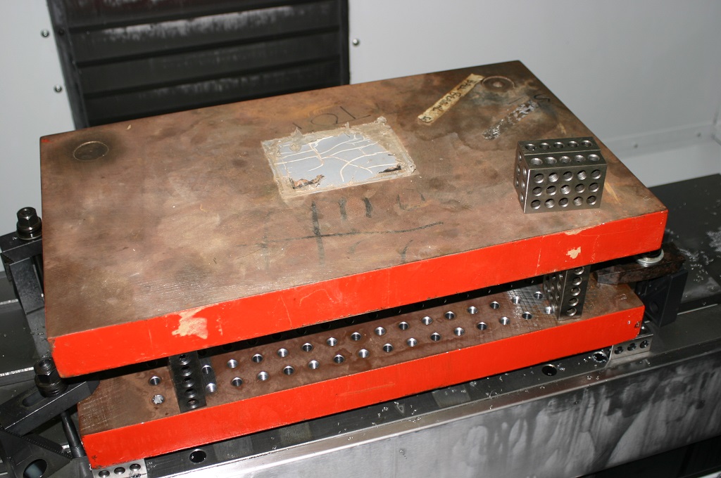
Things around the shop have been hectic. Videos have been taken of all the parts that have been made and I am going through them as fast as possible. However, here are some pictures of the progress on making the type 99 magazine.IMG_0545sThis is how live as a pressing die started out. This same size of block was used for both the top and bottom plates.


IMG_0542sThis is how it looked after rough machining. It still needs the finish pass. That is completed with 1/4″ ball nose end mill at .008 step over. Just the finish pass will take 1 1/2 hours.

IMG_0548sWith this picture you can see the resemblance to the actually magazine.

IMG_0554sThis is the finish male die. All we need to do now is de-bur and mount on the die plate.

Hope you enjoyed the update more coming soon.

next op on the front barrel support.

Well we have just about completed all the front barrel supports. So the next few posts will be videos of cnc machining the last two ops on the cnc lathe.

We have actually started on the rear barrel supports now.

Installing DRO’s on the lathe

I have taken a break from working on the VG1-5 project to upgrade a piece of equipment. This upgrade is being done on my little Chinese lathe. The brand name is Acra Turn and was obtain from a machine tool supplier that then went out of business, but it is just another Chinese type lathe that is available from numerous suppliers.

I initially installed a set of dro’s from CDCO out of Illinois (https://secure.sigma-star.com/cdcotools.com/index.php

IMG_0216s

They lasted less then one year, so while still under warranty the bad rail was set back. While inexpensive they were not worth the aggravation I went through to get a replacement rail. It took almost a year and numerous calls and finally a call to Home Shop Machinist ( http://www.homeshopmachinist.net/home?noredirect=true&noredirect=true) to get a new rail sent to me. HSM was great in there help and I cannot thank them enough. Also, to be honest my neighbor also bought a set of dro’s at the same time and I also obtain a second set for my other lathe and neither of the other ones have failed. When the new rail came in it was the wrong size and too large for my lathe and then the second rail failed. At this point I had just had enough.

I tried using dial indicators, but to be honest that gets a little old.

IMG_0005sa

I need to make 60 of the same parts and dro’s were the only answer. About that time MSC was having a sale on Mitutoyo dro’s ( whttp://www.mscdirect.com/?cid=ppc-google-Brand+Core+–+E_sWusaD5lR_msc_e_27864417304_c_S&mkwid=sWusaD5lR|dc&pcrid=27864417304&002=2167139&004=8097512824&005=42450341&006=27864417304&007=Search&008=&025=c&026=eb ) and while more expensive then the cheaper brand it was time to order a set.

IMG_0001s

The next 9 days was an interesting trial of aggravation. This is that story.

One of the problems with the little lathe is the carriage lock. It sets right up next to the cross slide and is hard to access in normal times and impossible to access with the dro installed.

IMG_0032ws

So a special lock was made to set flush on the carriage.

lock carrage sw


They still did not fit due to the height of the tool post and the height of the rails. There was no way to swing the tool post around. So now a spacer had to be made to raise the tool post.

IMG_0010s


The spacer had to be tall enough to allow the carriage lock to work and the tool post to swing around yet still not be too tall as to allow the center post of the tool post to come out of its corresponding hole. Once made it was surface ground to insure flatness.

IMG_0056s

Now new hold down bolts had to be made. With the additional height the older bolts would not work. So new tee nuts were fabricated and  threaded then  welded in place and then ground for a smooth fit. After look for thin nuts in the shop to match the all thread it was determined that the original ones would work. With a lathe that has all metric screws these were American standard.

Installing the dro’s required a .004 run out over 40” both parallel and linear.

11031101sc


This was the challenge. The first attempt was to attach the dro to the side of the lathe bed and just shim to the correct run out.

This did not work. It was attempted and every time it failed. Now I decided to install an aluminum block on the side of the lathe and machine it so the block was square and eliminating the draft angle of the bed casting. I don’t ever recommend doing that. Then just a block of aluminum was attached and shims were again used. Again, not so good.

IMG_0012s

The method that worked and allow us to bring it into spec was custom made brackets.

IMG_0019s

We made a set for the head stock of the lathe and for the tail stock.

IMG_0035s


Once the dro was installed and brought into spec then the center bracket was made and installed.

IMG_0011 (2)s

After the center bracket was installed  the dro was tested and still found to be in spec.

IMG_0021s

The only grip that I have is that the tie in for the wires only attach on the ends and not in the center. Thus making it difficult for the counter to set in place.

IMG_0034sws

Because of the weight of the small lathe and where it sat in the shop this project would not have been possible without the industrial skates from Northern tool. These are the  skates the made it possible (http://www.northerntool.com/shop/tools/product_200356890_200356890?isSearch=144020-1451).

IMG_0023s

So now the project is completed and the lathe back into it’s proper place we are back to working on the VG1-5 project. Stay tune for more updates.

Still working on the Front Barrel Support

We have continued with the front barrel support. The first three ops have been completed and now we are starting on op 4.

IMG_0361This picture shows what op 2 and 3 look like when completed.

IMG_0346s

This op is being completed on the small lathe with the new dro’s installed. The first step is to mill out the bottom of the larger hole to provide a flat surface for the spring.

IMG_0362sAs you can see in this picture I am using the end mill to one side and on direct on. I am not trying to open the hole just flatting the bottom of the hole.

IMG_0363s

Once completed we use a boring tool to open the hole to .006″ undersize then finish with a reamer.

IMG_0367s

IMG_0375sWhen all of the front barrel supports are completed we will be back on the cnc lathe to complete op 5 and 6. Hoping to be completed with that by the end of next week.

I hope you enjoyed this update and stay tune as we progress.

Quick update

By now everyone thinks that I have fallen of the end of the earth, not true. It has been real busy both with my life and in the shop. Just a couple of update photo’s of progress in the shop. First is that the first, second and third op’s are now completed on 20 bolts.

IMG_0200s

IMG_0358s

IMG_0357s

and the first and second op’s are completed on the front barrel support.

IMG_0346s

IMG_0347sSolid round stock on the left and completed 1st and 2nd op on the left.

IMG_0345sAnother bin of front barrel supports.

IMG_0356sFrom start to finish. We will be working on the rest of the turning ops this week and weekend.

Hope you enjoyed the update.


Making the VG1-5 Trigger Guard

Today we are going to stamp and machine the trigger guard. We start with a sheared piece of 2 mil sheet steel. Initially we tried 1 mil but found that it was to easily deformed. Next was 1.5 mil and still did not look correct. So 2 mil gave us the correct look without too much weight gain and was still workable. First, a short video of the process, and then we will look at each step with some photos…

Here are the pieces of starting material, cut to proper size:

IMG_0201s

After shearing the piece is de-burred, lubed and stamped in the forming die.

IMG_0028s

This is a look at the inside of the die.

trigger guard 1 (11)s

trigger guard 1 (10)s

trigger guard 1 (14)sThis is the look of the trigger guard after stamping.

trigger guard 1 (13)sThe interesting design feature of this dies is that I can us different lengths of stock to make different lengths of trigger guards. This allows the same stamping die to be used for different rifle projects.

trigger guard 1 (15)s

After stamping the trigger dies are set up in the fixture for machining and drilling.

trigger guard 1 (1)s

trigger guard 1 (2)s

Now the final look of the part.

IMG_0202s

Now all the trigger guards are completed.

IMG_0203s

In addition to being the trigger guard it is also the support for the bottom of the stock.

IMG_0191s

IMG_0189s

IMG_0188s

Hope you enjoyed this post and stay tuned for more on the VG1-5 build.

VG1-5 front barrel support

Here is the front barrel support. This part accomplishes a few objects. It supports the front of the barrel, is the guide for the recoil spring, acts as a seal for the escaping gas and locks the upper receiver together. So while a simple part to make the tolerances have to be maintained. This is a picture and solid model of the part.

R001-005 Front barrel bushing1

R001-005 Front barrel bushing2


There were two of these made and different methods were used to do it. The final method is the one that we will use when we cnc machine them for a production run. I must apologize in that I did not take a great deal of pictures while making this part. The time constraints required that it be made in a hurry to take this project to the next step.

The first method was to turn the out side to the proper dimensions then cut it off and bore and ream the inside.

IMG_0001s

IMG_0002s

IMG_0003sNow all this was completed using dial indicators. The dro has not been installed yet.

IMG_0005sa


While this method worked the concentricity was a little out, but still with in spec. So a different method was used the second time around. With this one I bored and reamed the inside of the part to the desire dimensions and then turn the out side between centers to. This allowed the inside and outside to concentric.

IMG_0019sAfter the part was machined it was then knurled and the front cut at an angle.

IMG_0021s

IMG_0025s

the final step is to cut out the locking groves. This was accomplished with a rotary table.

milling front barrel support 5 s

milling front barrel support 1 s

milling front barrel support 3 s

milling front barrel support 8 sNow this is the final test part.

IMG_0015swHope you enjoyed this post. I am a little behind on post, but up to speed on the project. In the last 2 weeks two test ( for function) barrels have been made as well as the gas piston. The rear top cover tooling has been made and  fitted. The trigger guard and safety attached. It is starting to look like a rifle. There is more to post so please stay tuned.

Heat treating video

I have an opportunity to interview the owner of the heat treating firm that I go to.A very knowledgeable gentleman that has been in the business for over 30 years. That being said I have always found heat treating to be one of the mystic black arts in the metal working trade. They do ferrous and non ferrous heat treating.  And they do terrific work. I have used them for years.

So here is my request. What questions would you like me to ask him?

We have an opportunity to learn a great deal, lets take advantage of it.

Just A quick note for todays post. I have spent the last two weekends building a barn for a friend so not a great deal of time to write a post. There is something not right about a 60 year old framer with a 65 year old helper.

There has been some work completed on the VG1-5. I will post about this later this week. For now it is enough to say that a computer generated solid model is only a starting point. When we completed the first two samples a couple of problems arose.

As for today I am at the surgery center for a little work on the knees and will be out of commission for the day.

I will post the machining of the test barrel, front and rear barrel supports and the problems encountered later. Thanks chuck