Here at Gun Lab. net we have been working on a number of projects. Quite a few videos have been made and as soon as I can get Ian down to help me correct the problems with Pinnacle studio they will be posted. Some of the projects are new stamping dies for various parts that have to be made and a number of them are the actual parts that are now completed.
I thought I would give you an up date on the rifle that we are currently working on.  This next batch of pictures deals with all the parts that have been made and the various stages that they are in.
 All the rear barrel supports are completed.
 All the hammers are machined but not heat treated.
 The cross pin for the rear barrel support is machined and threaded.
 All the front barrel supports are 90% machined. the retaining notch needs to be cut and that will be done after all the upper receivers have been machined.

 Misc cross pieces and been cut and stamped.
 The gas pistons are machined. We just received the tap in this week. We will have it threaded this coning week.
 All the rear sights are machined.
 All the extractors are here, we are using H&K extractors as they are the same basic style.
 All the extra extractor springs are here, again H&K.

 All the rear top covers have gone through the first stamping op and 20 or so have been completed.
 All the end caps for the rear top cover have been cut out,
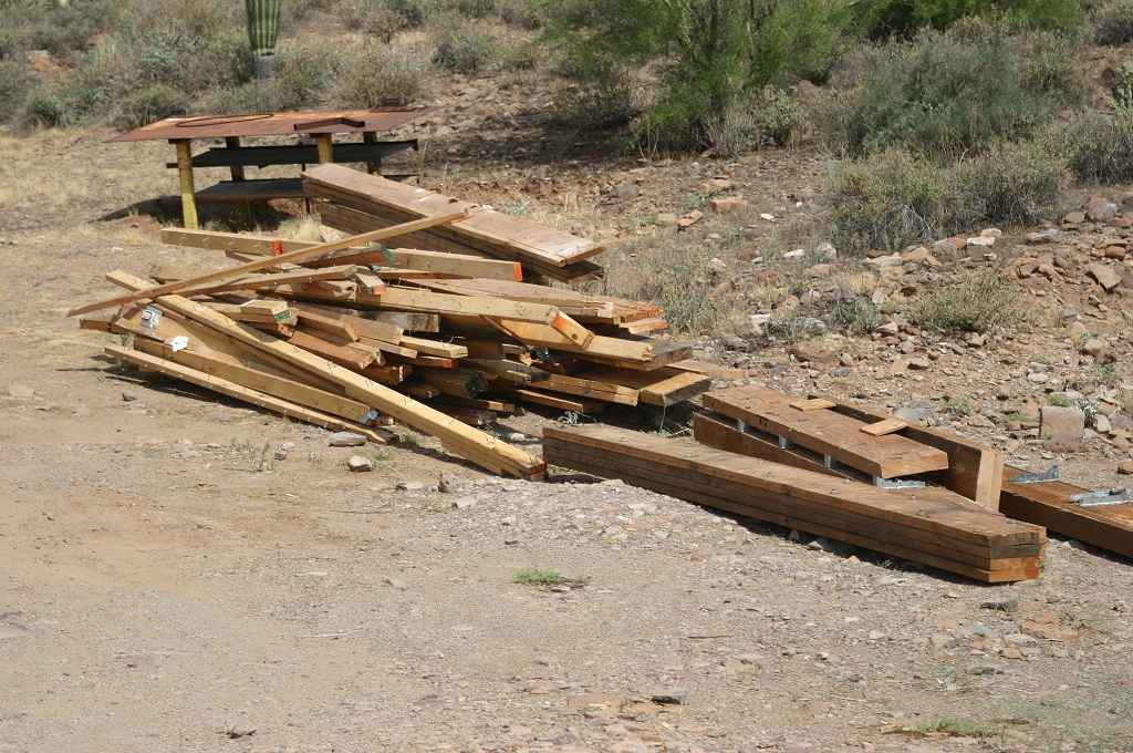
 All the barrel blanks are here. We are using MG-13 barrels are our basic blank. No they are not rusted just covered with grease and dirt.

 The receivers have been stamped.
 Mag catches are complete. The button and post are in the works.
 The triggers are completed and heat treated.
 The front barrel support take down spring are finished.
 The buffer springs are here as well.

 All the upper receivers are cut to length and turned to the proper diameter. And the first 10 are turn on the inside. Only one has been completed and fully machined. This our test and fit sample.
 The mag housings are completed.
 The upper receiver guides are machined.

 The test batch of the newly design primary and secondary sear and the new disconnector.
 The new fire control group housing is now design and ready for testing.
 All the strengthening plats are cut out and ready for bending.
 The newly design receiver support has been cut out, bent and tested for proper fit.


All the safety’s are cut out and just need to be bent.
I have more pictures to take for the rest of the parts that are completed. I will update soon.