Not a big post for today, just an update on the projects we are working on.
First and most important is the VG1-5 project. I received a call this afternoon late that the firing pins can be picked up from the heat treating firm. With this last piece we can send the second rifle to the ATFE for final testing. The second item on the VG project is that all the receiver flats are in the spot welding room and as soon as we modify the spot welders they will be on the line to finish. That will be this week.
The drawings for the MP-44 trunnions are solid modeled and material is ordered so we can finish that project.
The Japanese type 96 and 99 magazines have taken a step back. The first two stamping dies did not work as planed and we needed to send the magazines back. They are still on the drawing board as I need them for my own guns.
The AR-16 is still being solid modeled. We are getting closer but still more time is needed to finish this project. I only work on it when I have spare time and we know how that goes.
A member of our family here at Gun Lab located me an isolation transformer and with that I hope to get the wire edm powered up.
We have been doing a reverse engineering project on a German WW2 machine gun which is coming along nicely and I hope to have drawings in the near future and a solid model shortly after that. This project has been a real ball buster, but with the use of the schools cmm we are getting close now.
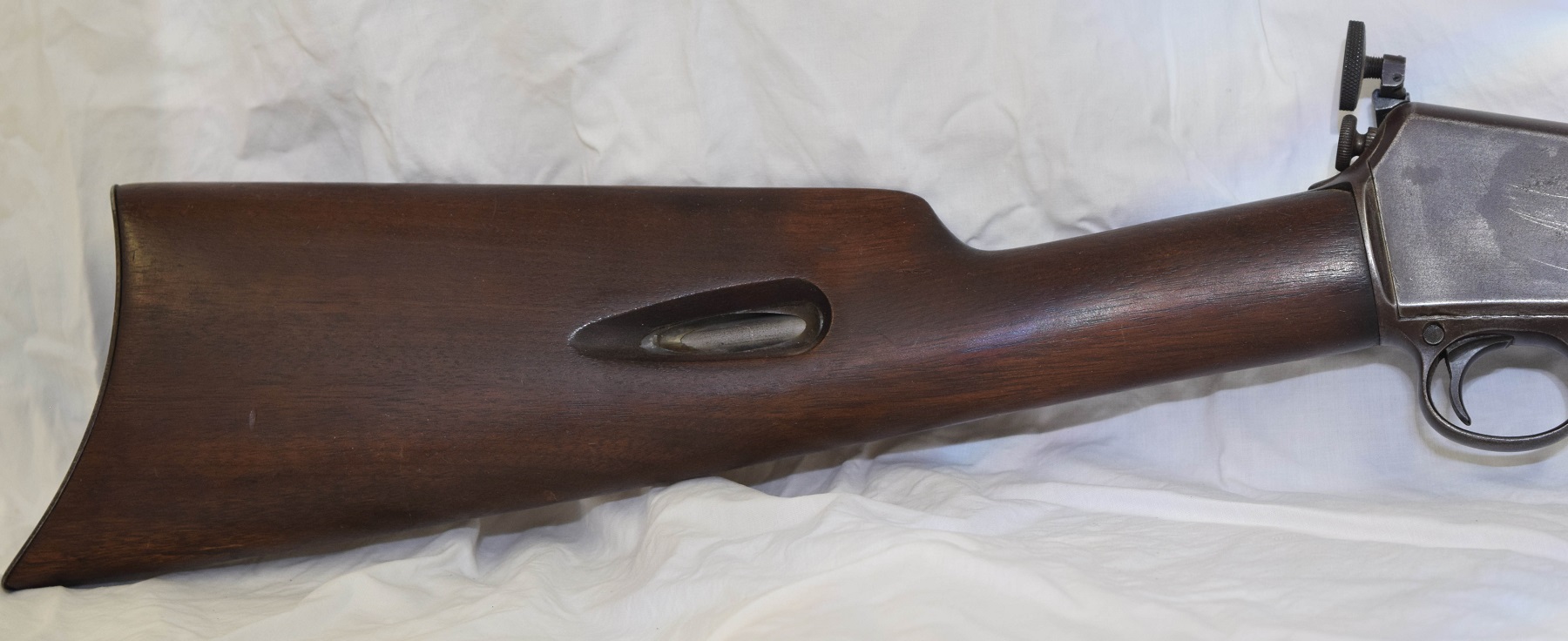
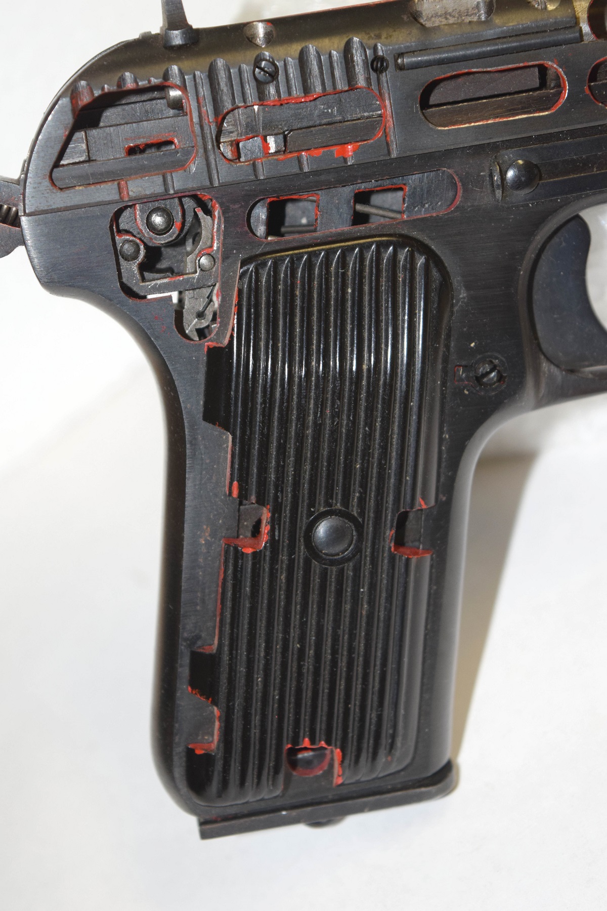
I am currently work on a few write ups for the site. Part 2 of the Winchester self loaders should be dome this week, a friend , O.H., is sending me some interesting photo’s and scan’s on a few weapons to post and the third installment on the Bushmaster pistol is in final editing.
This should answer all the questions that have shown up in my in basket. If there are any other question please feel free to drop me a line.
I do need help with a project though. I need manuals for the wire EDM. I am concerned that the batteries have died in the controller and I am going to have to reset the parameters. This machine came with no manuals at all. Here are a few pictures of the panels and model numbers.


 Xerox copies are fine. I just need to learn about the parameters and set up of this machine. Thanks everyone for helping.
With nothing else going on I am going to hit the rack, tomorrow is another fun filled day for me.