Categories

Still working on the Front Barrel Support

We have continued with the front barrel support. The first three ops have been completed and now we are starting on op 4.

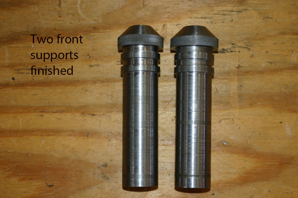
IMG_0361This picture shows what op 2 and 3 look like when completed.

IMG_0346s

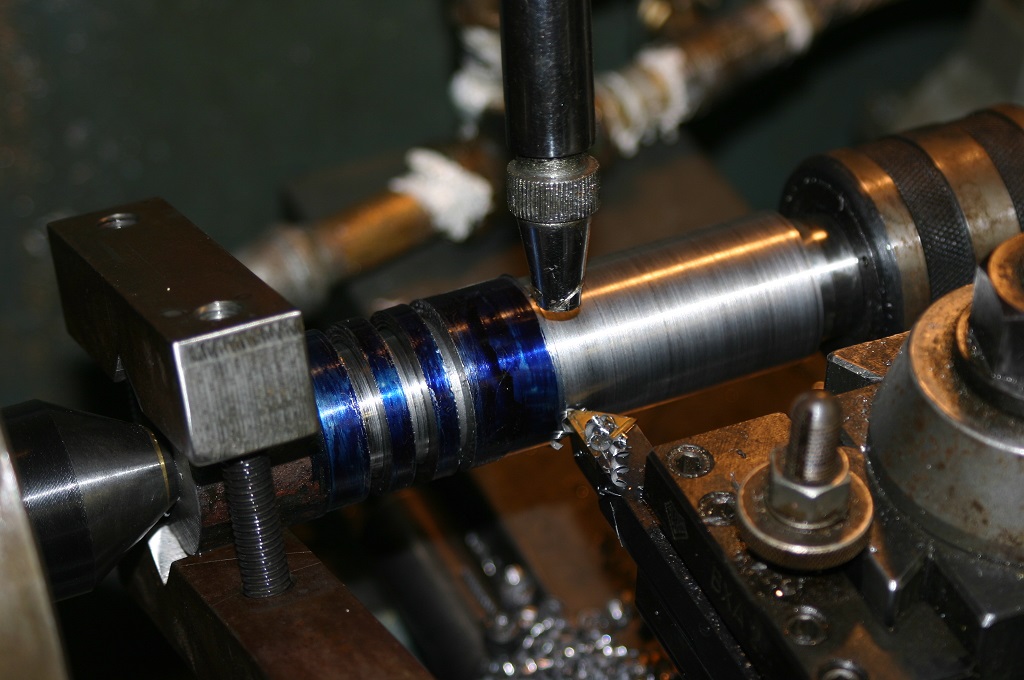
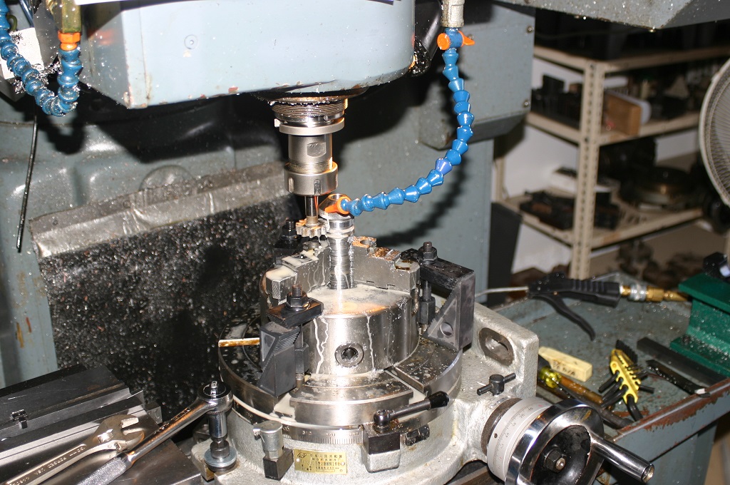
This op is being completed on the small lathe with the new dro’s installed. The first step is to mill out the bottom of the larger hole to provide a flat surface for the spring.

IMG_0362sAs you can see in this picture I am using the end mill to one side and on direct on. I am not trying to open the hole just flatting the bottom of the hole.

IMG_0363s

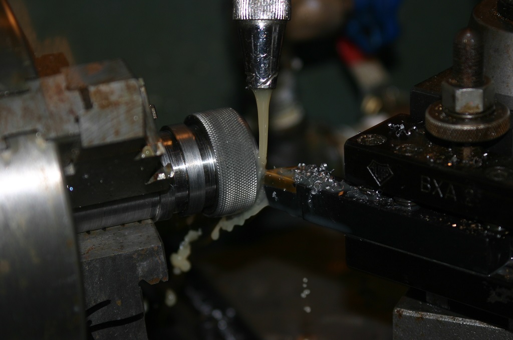
Once completed we use a boring tool to open the hole to .006″ undersize then finish with a reamer.

IMG_0367s

IMG_0375sWhen all of the front barrel supports are completed we will be back on the cnc lathe to complete op 5 and 6. Hoping to be completed with that by the end of next week.

I hope you enjoyed this update and stay tune as we progress.

Quick update

By now everyone thinks that I have fallen of the end of the earth, not true. It has been real busy both with my life and in the shop. Just a couple of update photo’s of progress in the shop. First is that the first, second and third op’s are now completed on 20 bolts.

IMG_0200s

IMG_0358s

IMG_0357s

and the first and second op’s are completed on the front barrel support.

IMG_0346s

IMG_0347sSolid round stock on the left and completed 1st and 2nd op on the left.

IMG_0345sAnother bin of front barrel supports.

IMG_0356sFrom start to finish. We will be working on the rest of the turning ops this week and weekend.

Hope you enjoyed the update.


Making the VG1-5 Trigger Guard

Today we are going to stamp and machine the trigger guard. We start with a sheared piece of 2 mil sheet steel. Initially we tried 1 mil but found that it was to easily deformed. Next was 1.5 mil and still did not look correct. So 2 mil gave us the correct look without too much weight gain and was still workable. First, a short video of the process, and then we will look at each step with some photos…

Here are the pieces of starting material, cut to proper size:

IMG_0201s

After shearing the piece is de-burred, lubed and stamped in the forming die.

IMG_0028s

This is a look at the inside of the die.

trigger guard 1 (11)s

trigger guard 1 (10)s

trigger guard 1 (14)sThis is the look of the trigger guard after stamping.

trigger guard 1 (13)sThe interesting design feature of this dies is that I can us different lengths of stock to make different lengths of trigger guards. This allows the same stamping die to be used for different rifle projects.

trigger guard 1 (15)s

After stamping the trigger dies are set up in the fixture for machining and drilling.

trigger guard 1 (1)s

trigger guard 1 (2)s

Now the final look of the part.

IMG_0202s

Now all the trigger guards are completed.

IMG_0203s

In addition to being the trigger guard it is also the support for the bottom of the stock.

IMG_0191s

IMG_0189s

IMG_0188s

Hope you enjoyed this post and stay tuned for more on the VG1-5 build.

VG1-5 front barrel support

Here is the front barrel support. This part accomplishes a few objects. It supports the front of the barrel, is the guide for the recoil spring, acts as a seal for the escaping gas and locks the upper receiver together. So while a simple part to make the tolerances have to be maintained. This is a picture and solid model of the part.

R001-005 Front barrel bushing1

R001-005 Front barrel bushing2


There were two of these made and different methods were used to do it. The final method is the one that we will use when we cnc machine them for a production run. I must apologize in that I did not take a great deal of pictures while making this part. The time constraints required that it be made in a hurry to take this project to the next step.

The first method was to turn the out side to the proper dimensions then cut it off and bore and ream the inside.

IMG_0001s

IMG_0002s

IMG_0003sNow all this was completed using dial indicators. The dro has not been installed yet.

IMG_0005sa


While this method worked the concentricity was a little out, but still with in spec. So a different method was used the second time around. With this one I bored and reamed the inside of the part to the desire dimensions and then turn the out side between centers to. This allowed the inside and outside to concentric.

IMG_0019sAfter the part was machined it was then knurled and the front cut at an angle.

IMG_0021s

IMG_0025s

the final step is to cut out the locking groves. This was accomplished with a rotary table.

milling front barrel support 5 s

milling front barrel support 1 s

milling front barrel support 3 s

milling front barrel support 8 sNow this is the final test part.

IMG_0015swHope you enjoyed this post. I am a little behind on post, but up to speed on the project. In the last 2 weeks two test ( for function) barrels have been made as well as the gas piston. The rear top cover tooling has been made and  fitted. The trigger guard and safety attached. It is starting to look like a rifle. There is more to post so please stay tuned.

Heat treating video

I have an opportunity to interview the owner of the heat treating firm that I go to.A very knowledgeable gentleman that has been in the business for over 30 years. That being said I have always found heat treating to be one of the mystic black arts in the metal working trade. They do ferrous and non ferrous heat treating.  And they do terrific work. I have used them for years.

So here is my request. What questions would you like me to ask him?

We have an opportunity to learn a great deal, lets take advantage of it.

Just A quick note for todays post. I have spent the last two weekends building a barn for a friend so not a great deal of time to write a post. There is something not right about a 60 year old framer with a 65 year old helper.

There has been some work completed on the VG1-5. I will post about this later this week. For now it is enough to say that a computer generated solid model is only a starting point. When we completed the first two samples a couple of problems arose.

As for today I am at the surgery center for a little work on the knees and will be out of commission for the day.

I will post the machining of the test barrel, front and rear barrel supports and the problems encountered later. Thanks chuck

My Introduction

Introduction

Now that you have following along with this build I guess it is time to introduce myself. By now you know my name is Charles, however after someone meets me they generally just call me Chuck. So, on this site just call me Chuck.

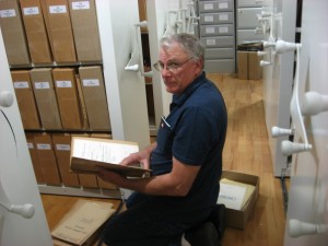
I have three passions in my life. The first is my wife of 33 years. Generally if you see a picture of me it was taken by her. She feels that there should be a human touch on this site and not just gun pictures. Not only is she my wife, she is my best friend, and travel companion. During my trips to study small arms she will spend a great deal of time copying information for me, which allows more time for me to do research and take pictures.
IMG_2837s

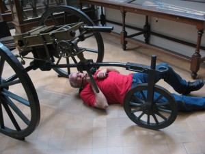
The second is small arms. My earliest memories are of guns. While living in Europe as a child I can remember trading cigarettes for old guns and then getting in trouble for it. I bought my first gun when I was 14 after I moved to the states. I have been studying and collecting them ever since. I enjoy all types of small arms. From cheap single shot pistols to the most expensive double guns and machine guns. Not only do I study them, I enjoy doing everything related to guns; from buying parts for weapons that I will never own to buying books on them. My library is about 3,500 books and magazines, a number of them in languages that I will never be able to read. I have had the opportunity to meet some of the greatest gun designers and collectors and have enjoyed the experience. A few of them I consider my closest friends. When the finances allow it, my wife and I travel the world to photograph and study weapons. I do not go anywhere without my measuring tools and camera, and if allowed, will take hundreds of pictures of a single weapon.
IMG_2791s

IMG_1961 cropped and written

IMG_1973crop

My third passion is machining. I have loved working with wood and metal all of my life. I bought my first tool when I was not even a teenager and have been buying them ever since. I have what I would call a nice advanced home shop where I play every chance I get. In the future we will take a tour through it and chat about each of the major items and what they are used for. With that being said, I do not know everything about machining. I consider myself to be an advanced amateur and I try to learn something new every day. In addition to just buying machines, I also build or modify a number of them. Expect to see that on this site as well. So everything is not just guns but also the equipment necessary to make them. A number of articles will deal with the fixtures and tooling necessary to build a weapon. With the advent of the CNC machinery that my shop has up-graded to, we will also cover manual machining, forging, casting of non-ferrous material and welding.

32-DSC_4275-620x430written

Now for the rest of the story; I own two businesses and generally work 12 to 14 hours a day. I will attempt to post at least two to three times a week as the builds go along. English is not my strong point, so if your comments are to bang me on that, just don’t. Also, with all the photographs I take, you would think that I would have improved over the years. I have not. Thank God for digital cameras because they allow me to take enough pictures that something will eventually turn out okay.


This site is going to deal with the design and manufacturing of small arms. I have a weapon manufacturing license and a SOT license.  What this means is that I can build and register any weapon except a destructive device. There a number of projects in the works and I generally work on 3 to 4 at a time. We will be covering these projects from concept through the final product. The modeling program that is used in my shop is ‘Solid Works’ and the cam program is ‘Master Cam’. Everything will be discussed from the good designs to the real mess-ups that I can do on occasion.  A number of the projects have a quite a few revisions to get to a part that will work. During a project I will attempt to post a link to where I obtained the equipment, or material, thus making it a little easier for you as well.

This site will be picture, and eventually, video heavy. It is just a lot easier to explain something that way then with just words.

I hope you enjoy the projects and I will attempt to answer any questions that I can. There are a few things not to do. Do not ask me for engineered drawings. Most of the items that will be built here have no drawings and I have spent years reverse engineering them. Also, I will not post engineered drawings on this site because it is a worldwide site and some countries do not allow their citizens to have access to that kind of information. I do not sell partial builds, everything I make is to completion. It has to be heat treated and proofed to verify safety.

I have known Ian from Forgotten Weapons for years and was part of the starting process to get Forgotten Weapons up and going. It is Ian’s site and he has done a great job with it. Ian will be helping me with this site as well.

I hope you will enjoy this site and learn something from it. Please feel free to comment and ask questions. If anyone knows of a manufacturer that would not mind being interviewed, please let me know.

Chuck

Making the Type 99 magazine part two

Well more work has been completed on the solid model of the type 99 magazine. We have now finished both side with feed lips and bottom plate rib. Soon the follower and lower spring plate will be completed. When all the parts are completed it will be off to the 3-D printer.

Here are a few more solid models to check out.Type 99 Mag Assy1

Type 99 Mag Assy2

Type 99 Mag Assy4

Type 99 Mag Assy34

We have now completed the entire magazine. So this is the rest of the solid models.

First the exploded views.

Type 99 Mag Assyexplode1

Type 99 Mag Assy explode2Now for some individual parts.

rienforcment stop

Spring Holderand a picture of this part.IMG_0086

Type 99 Followerand a picture of the followerIMG_0075

spring holder pinHere is a drawing of the magazine as well.

Type 99 Mag Assy3print1

This is it for now. Next will be the machined plastic model.

As a side not. If anyone has a rusted/dented unrepairable magazine they want to donate to the cause it will be used to test the final bit of information that we need. Please feel free to contact me.

Part 4: VG1-5 Rear Top Cover

We are going to take a short break from the lower receiver and do some work on the upper rear top cover. This piece is what holds the ejector in place and covers the rear of the upper receiver.  In the original rifle it also contained the fire control mechanism. Due to the changes that we made to the fire control system it is now installed in the lower receiver.

In the first model reproduction this piece was made with only a single rib.

first and second model top covers small

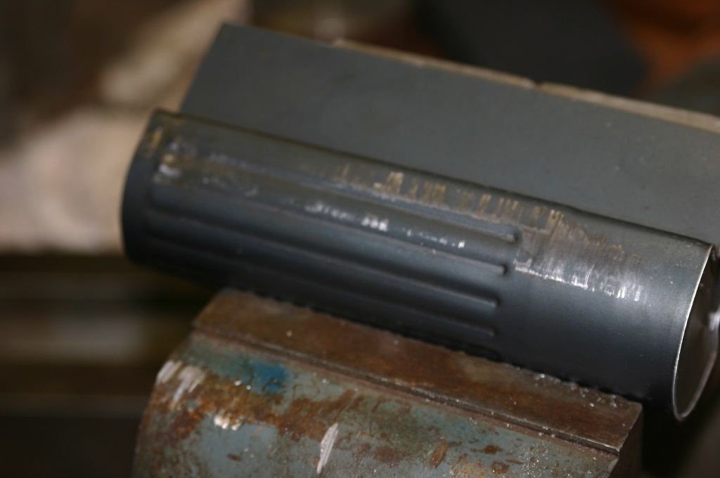
However in this model we are going back to the 7 rib design as in the original. I just think it looks better and more like the original.IMG_0194saThis is the story of making that pressing.

Pressing is an interesting art and science. While we do everything in solid works their sheet metal program is not actually designed for this type of work. A lot of steps were taken to get to the design that we wanted.

In this first picture is the basic sheet steel cut out that we started with to test the new stamping dies that we made for the pressing of the ribs.

basic 1 st model flatsThis is a far way from what the actual design will be when we stamp for the top cover.

Here are a few pictures of the top cover rib stamping dies.

IMG_0007sIMG_0175saThis what the stamping will look like just out of the die.

IMG_0011sa

Nothing ever turns out as it suppose to during the first pressing. We had are share of up sets.IMG_0001 (4)written

With the rib design correct and the overall shape correct it was time to test out the next step. This is to bend it into the correct shape for the rear top cover.

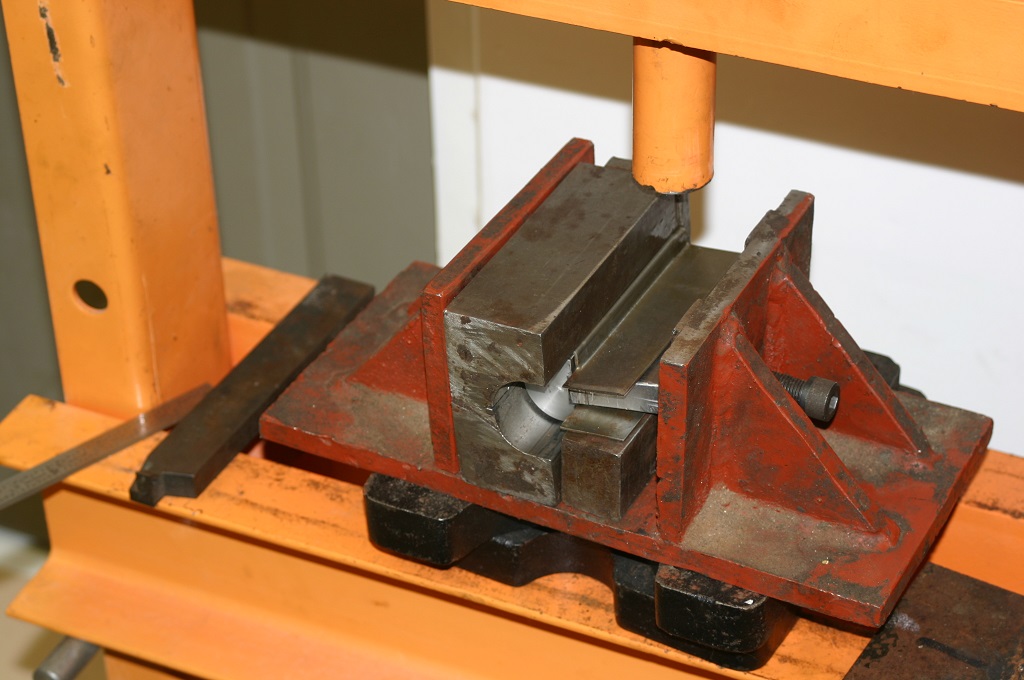
This next series of pictures is the actual bending of the top cover. This series was to test the actual die out and before it was installed in a set of die plates.

IMG_0001These two pictures deal with setting up the flats in the press dies by correctly placing it to bend it.

IMG_0002Once correctly located the pressing continues.

As a quick side not. The press used in this operation was a 20 ton from Harbor Freight.

IMG_0014 (2)s

IMG_0015s

IMG_0016s

IMG_0017s

IMG_0018s

IMG_0019s

Once through this operation the flat will come out with a rounded shape.

IMG_0183s

But the work does not stop there. Even though it has a basic shape it still needs to sharply defined. This next set of steps shows that being done.

IMG_0021

IMG_0044s

IMG_0046a

IMG_0024sYou will notice that several hits are done during this stage. This is to insure that the lower flange is pressed square for the entire stamping.

IMG_0023sNow that it is pressed tight it is taken out of the die and its support and this is what we have. Still a great deal of work to be done to it. In addition it is not quite the correct overall design.

IMG_0029

The next post will deal with more on the upper rear top cover. I hope you enjoyed this presentation so far.

Making the Japanese Type 99 Magazine

An opportunity has come about to possibly buy a Japanese Type 99 Nambu light machine gun. Years ago I owned one and enjoyed shooting it. I still have ammo and reloading equipment and kind of always wanted to obtain another. The problem with Japanese machine guns is the lack of spares and magazines. I bring this up because there are no magazines for the gun that might be available and it is missing a few small parts. Luckily though I have a friend who owns a Type 99 with one magazine. So a deal was struck. Let me borrow the magazine and the parts I need to make and I will make him a few magazines as well.Now with the magazine in hand it is time to get down to brass tacks. The first order of business is to study the magazine closely.

IMG_0001 (2)sThis allow me to determine how it was made.

After the examination was complete it was time for picture taking. A hundred pictures or so later…

IMG_0002 (2)s

IMG_0004s

IMG_0031sThese are just a few.

Then a set of drawings were roughed out so I could make a solid model. This is the start of that model.Assem1This gives me the two halves of the magazine. The next order of business will be to design the feed lips. That will be in the next day or so depending on work load.