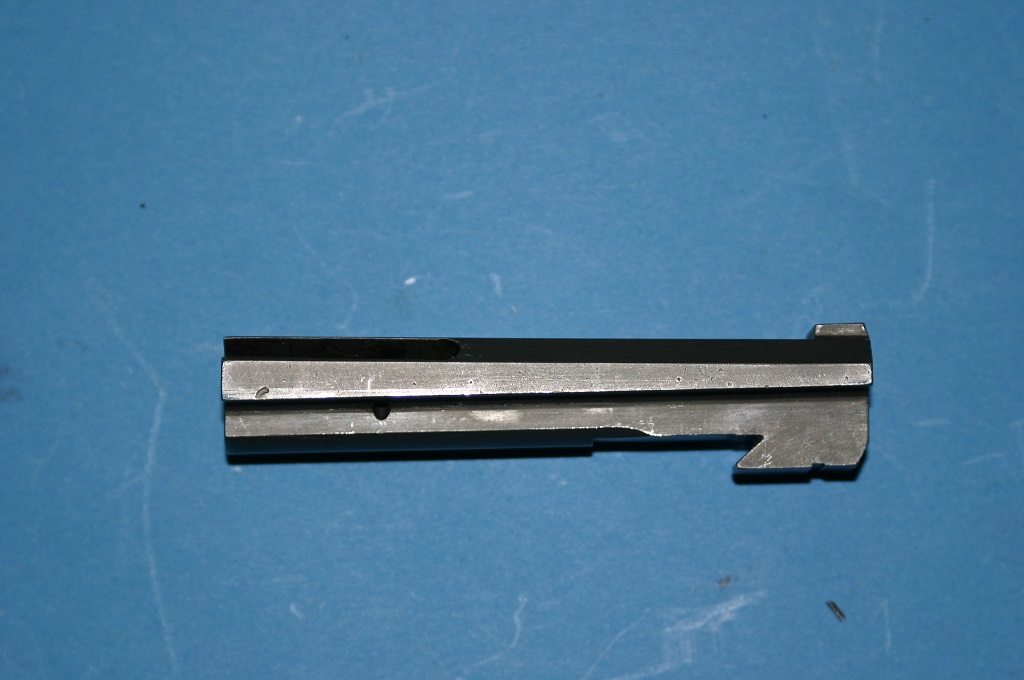
The picture from the post on 11-8 is from the bolt of a Beretta model 1957 carbine in .30 M1.
Here is the write up on it from the book ” The World’s Assault Rifles”. This is another book you should have in your library.


|
The picture from the post on 11-8 is from the bolt of a Beretta model 1957 carbine in .30 M1.
Here is the write up on it from the book ” The World’s Assault Rifles”. This is another book you should have in your library.
Another interesting part.
A rifle that I have been interested in for quite some time is the EM-2. It is one of those rare rifles that you read about but generally don’t have a chance to see, examine or shoot. I have had the opportunity to do all three. To start all of the rifles came with a fitted wooden box holding the rifle and it’s accessories.
So lets chat about this set up. First thing is that the rifle is a bull pup design and was initially made in .280 and later made in what was to become the NATO standard, 7.62×51.Here is a picture of the two of them together.
The machining on this rifle is something to admire.
Here is a video for papa Joe of me shooting the EM-2. Enjoy papa Joe you could have come with me.
Stay tune for the next part of the EM-2 saga.
During our recent trip through the mid-west I had an opportunity to stop in and chat with John D.,a metallurgist, and Joe P.,a heat treating professional. I ended up taking a number of pictures and John was nice enough to do a write up for me concerning what we looked at, what it does and how it works.
Nikon inverted stage ‘Optiphot’ optical metallurgical microscope with a CCD camera and flat screen display for group viewing.. This type of reflected light microscope is usually referred to as a ‘metallograph’. Metallographs provide useful magnifications from 10x to 1,000x plus and are distinguished from most scientific microscopes by their use of reflected light, rather than transmitted light. The illumination light is introduced into the image axis via a half silvered mirror and broadcast upon the sample surface by the objective lens, the same objective lens which generates the reflected image.. Image on the flat screen is a polished and etched, through hardened, medium carbon, manganese-chromium alloy steel transverse section (cut perpendicular to steel rolling direction). Area being viewed is deep in the sample, away from its quenched surface. This steel sample image reveals decided chemical segregation remaining from its original solidification at the steel mill. The light yellowish blotches are alloy rich ‘strands’ in the steel which fully hardened to martensite at this depth from the quenched surface. The darker greenish envelopment is the much softer, alloy depleted matrix which did not fully transform to martensite (the strong, hard constituent of hardened steel) at this depth. This type of alloy segregation is termed ‘banding’ by metallurgists and can severely degrade mechanical properties in the directions perpendicular to steel rolling. Banding in alloy steels can be diminished by greater reductions in steel mill hot rolling (requiring a larger initial size cast form), or adding alloying elements like nickel which promote more chemically uniform solidification. Banding is a major issue in the AISI/SAE 4140 series (chromium-molybdenum) steels popular in American firearms construction. It is also a major issue in the manganese and manganese-chromium steels popular for firearms construction in Europe.
Fully automated Newage ‘MT-90′ microhardness test system used to measure the hardnesses of very small volumes in metals. Microhardness is usually measured on the Vickers or Knoop scales using single indentation loads ranging from 100 grams to 2.5 kilograms. Microhardnesses are determined by measuring the width of impressions made by known dimension diamond penetrators. Microhardness testing – due to its inherent sensitivity – can only produce accurate hardness measurements on highly prepared (polished) surfaces. The more commonly used Rockwell scale differential-depth (dual load to eliminate instrument lash) hardness values are determined by directly measuring the depth of penetration, using indentation loads ranging from 60 kg to 150 kg. Microhardness measurements can be converted to the more commonly understood Rockwell values by using conversion tables, but the microhardness measurements only read the hardness to a depth of about 0.1mm, while Rockwell measurements routinely read the hardness to a depth of 1mm. This is an important distinction when evaluating metals with hardness gradients. Side note: the indispensable Rockwell hardness test is 100 years old this year, having been invented in 1914.
At the top of the lower right quadrant in this screenshot from the Newage MT-90 automated microhardness tester, you can see what metallurgists call a ‘microhardness traverse’. This shows the gradient in hardnesses from near the surface, towards the interior, in a carburized steel section. The surface of the steel sample is directly under the center cross of the quadrants. The material imaged to the left of this point is a phenol formaldehyde plastic mounting compound (‘bakelite’) used to preserve flatness of the metallurgical specimen during polishing. The material imaged to the right of this point is the actual steel metallographic specimen. The light area at the surface is extremely hard, high carbon martensite which has fully transformed. As the steel darkens away from its surface, its carbon content is lower and hardness is declining due to reduced hardenability and less transformation to martensite. [Hardenability is a direct function of carbon content in this case]. The individual HV(1kg) impressions are increasing in size further from the carburized surface, reflecting declining hardness. This particular traverse has been performed to determine ‘effective case depth’, the depth below a carburized surface where hardness falls below 50 Rockwell ‘C’ scale equivalent [the term equivalent is used to indicate that the original measurements were not performed using the Rockwell ‘C’ scale]. Effective case depth is the most important property of precision carburized steel parts. Core hardness and percentage of retained austenite (a soft constituent) in the case are the other two commonly specified properties which influence part performance.
Metallographic image of an etched section through fully hardened and then tempered medium carbon steel specimen without a carbon gradient. Bakelite on the left, steel on the right hand side. A good metallographic structure not evincing much evidence of banding, such as might be obtained from AISI/SAE 8645 or 4340 nickel containing steels. The faint striations visible are polishing artifacts which do not reflect upon the actual sample structure.
Another view of the Nikon ‘Optiphot’ inverted stage metallurgical microscope. The sample being viewed is in the exact center of the square stage, in front of the binocular eyepieces, on the round white metal stage insert. The sample is fully encapsulated in bakelite, which is also seen on the left side of the flat screen screenshot.
John Dingell, III, Charles Kramer, and Joseph Pieprzak, Jr. discuss the metallurgy of several firearms parts and assemblies. Note the VG.1-5 rear assembly to the left of the reading glasses; can anyone recognize the shiny bolt to the right of the reading glasses? Hint: it is from a firearm that could be politely described as Chuck’s obsession! A few other pictures testing the shiny bolt thing.
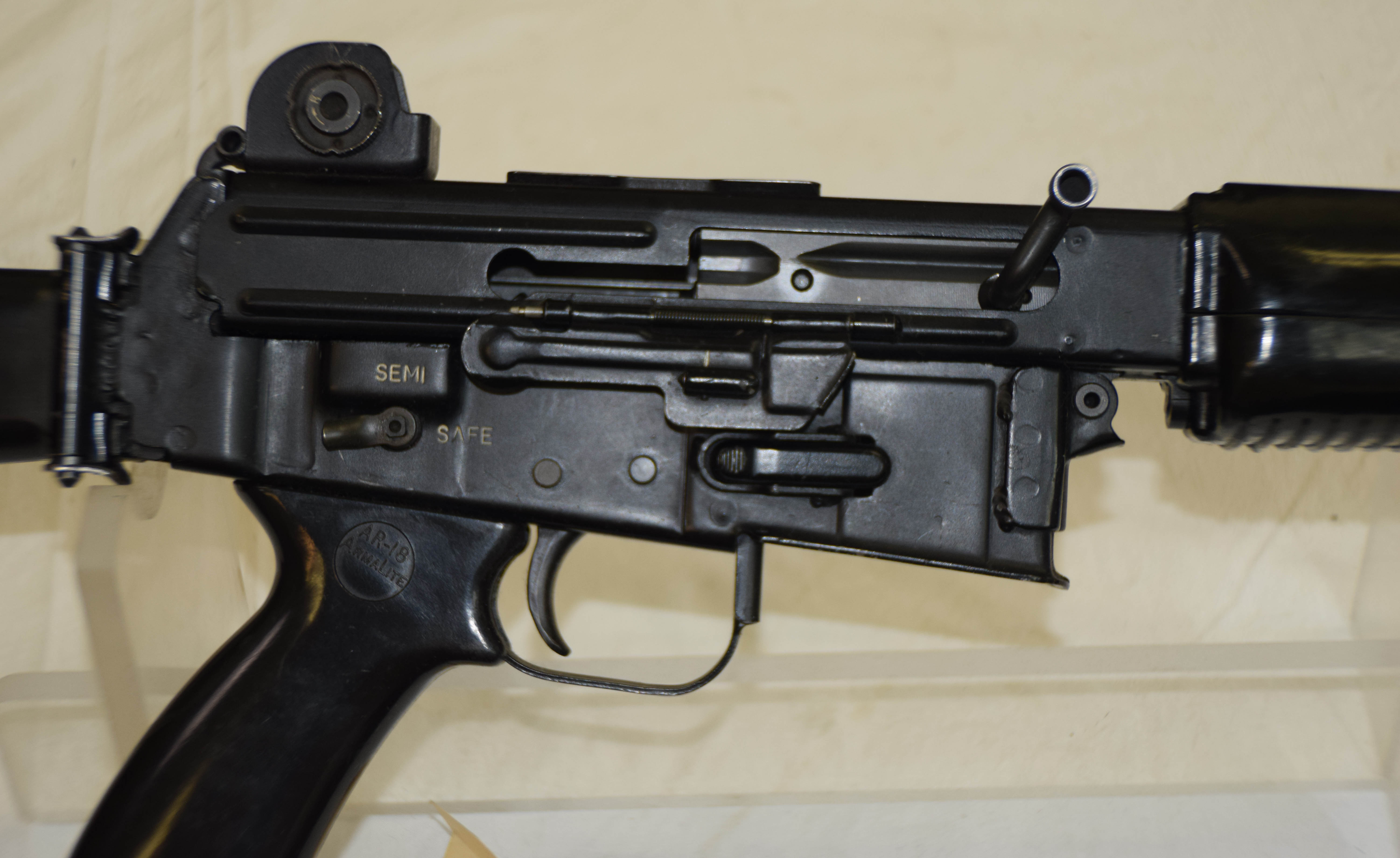
Thanks to John for adding the technical aspect for this write up. You will get extra brownie points for guessing the shiny thing. I am always interested in how weapons are made, a major reason for this site. So when I had the opportunity to stop at a friends house on this last trip to look at components of the AR-180 in in various stages of manufacture I jumped on it. For those of you that do not know what a AR-180 is here are a couple of pictures.
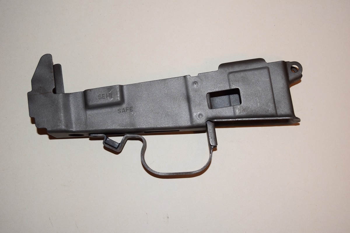
The Ar-180 is a gas operated multi-lug sheet metal stamped rifle. Eugene Stoner is one of the designer of it and it was design to be produced in countries that did not have a strong manufacturing sector. To me it is interesting to see the steps necessary to make this weapon. I don’t have all pictures of the different stampings however there are enough to see how it is made. So lets start with the lower receiver. This first set of pictures is the completed cut out flat prior to any press shaping.
This next series of photos show the initial pressings that are put in for the magazine housing.
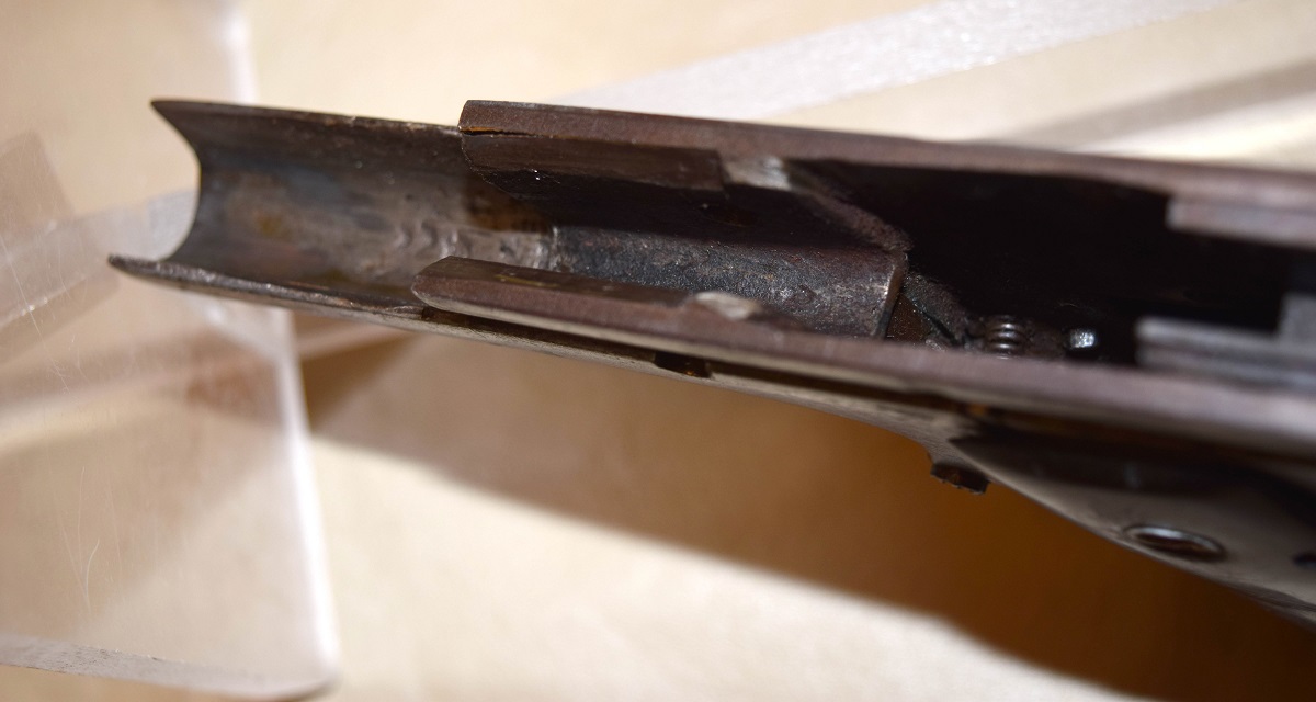
this next series shows what is now looking close to a complete lower receiver. This is where it gets a little confusing. There are samples showing different states of completion. This leads me to think that the holes for the fire control group were drilled in and done on a fixture. These next series of photos will show three different lowers some with holes and some without.
Now there are a variety of answers for these differences. The first is that the AR-180 went through a number of changes as to design and manufacturing methods. The second is that samples were pulled from the line as example board production steps. The third is that they were manufacturing examples for the floor personnel. This concludes this portion. In the next installment I will show the upper receiver being made.
A number of items were worked on this weekend. Another section of the fab shop ceiling was completed as well as the out side cover for my forge exhaust.
The last item worked on was the stocks for the VG1-5. The have been roughed out and ready for the final machining.
That is it for this weekend. I have also written a few other up coming posts and now time to relax. For those of you that correctly knew the answer give your self a gold star. It is the winter trigger for a EM-2. Here are a couple of references from Thomas B. Dugelby’s book EM-2 concept and Design. This book is published by Collector Grade Publications and should be in your reference library.
This is going to be a difficult one but fun.
I had a little extra time this morning so out to the shop it is. Wrote the program and go the mill warmed up and spent my free hour cutting out the guide slot for the fluting machine. Here is a quick video of the process.
A couple of pictures.
On my trip through the mid-west I happen to have an opportunity to examine a Viet Cong copy of a 1911 pistol.
You can learn a great deal studying arms made with just basic tools. The first is that you can do anything with a file, chisel and hack saw. That is how this gun was made. It is crude and I am not real sure that it is safe. However, the owner did say that he has shot it with much reduced loads. This pistol has seen some rough usage, jungle life and all.
The barrel to slide fit up is not great.
|
||
|
Copyright © 2026 GunLab (KnownHost) - All Rights Reserved Powered by WordPress & Atahualpa |
||