We have completed some more work on the new stamping dies. We changed the design from a single stamp stamping set up to a multi step process. The first step is to stamp the ribs in the sheet metal then the following die set captures the sheet metal using the ribs as a reference and then bends the side walls.
This is the first set of dies. A little more still needs to be completed to work out the sheet metal stops.
The next set will start the bending of the sides. This is the series of parts required for this die. At this point the die is not complete. We still need to finish the upper and lower attachment plates.
the other side of the bending die.
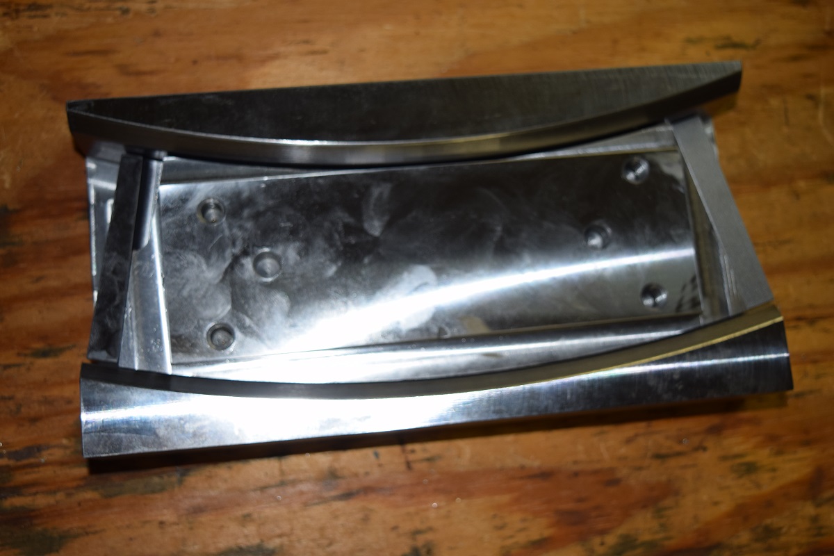
As they look together.
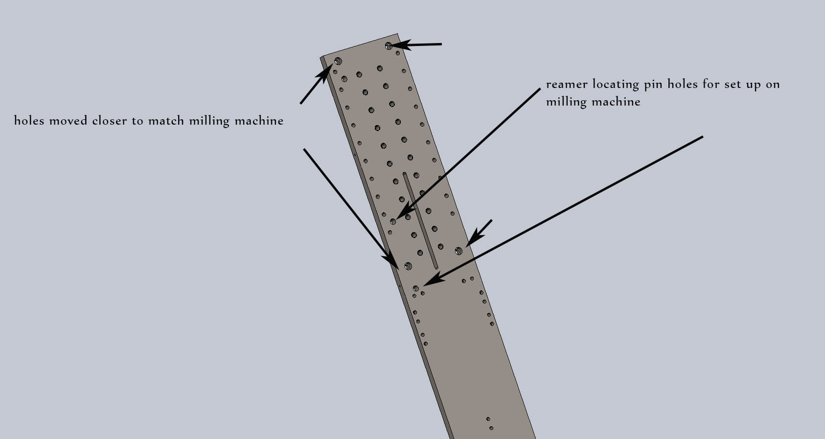
The back side of the die . The hole are for alignment and springs.
This series of pictures starts to show the die as it would be assembled.
These are the end pieces of the stamping die to form the top and bottom of the magazine.
I hope you enjoyed the update. We are hoping to have this die completed this week. The material just came in on Friday. As always commits are appreciated.
Well the fab shop new addition is now framed up and ready for a concrete pour. With any luck I will have the concrete completed in October.
This weekend is also honey-do weekend as well. The tile needed to put down in the hallway and bathroom and the new lighting installed. This is by the end of Friday night.
This is the progress by Saturday night.
And the progress in the bathroom.
This is the end at Sunday night for the hall.
And the bathroom.
The hall lighting was installed as well.
The fun task is the solid works class that we put on for my friend from Texas. He is scheduled for a stop over here for a couple of days with his job, so it is time to learn and do a project. In this case we are working on the fluting press and a set of back grips for his semi 1919.
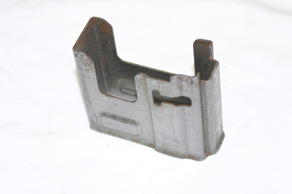
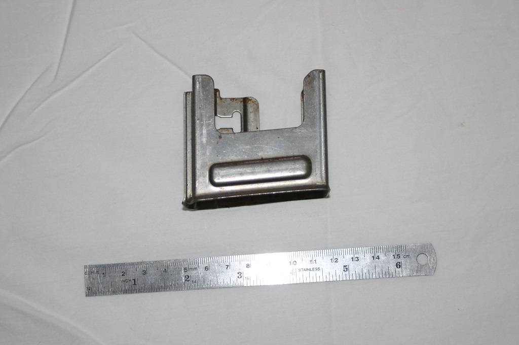
More work has been completed on the Japanese 99 magazine.
We are also working in the fab shop. There is a lot to be completed in here to allow me to go forward with the projects. The first item completed is the band for the bracket to hold up the vent exhaust tube for the forge area.
And a close up.
After the clamp the supports were made.
The complete assembly up and in place.
Now with the tube installed.
On to the next project. I have a section of 1″ steel plate that has a few supports welded on it. This will be cut up and machined for the necessary components needed for the fluting machine.
A little close up of the welded supports.
After all the supports are removed and ground the plate looks like this. A simple project that tool several hours and was way to much fun. This was accomplished with a cutting torch and a couple of grinders.
Then it was time to lay out for the necessary parts. This next phase of the project was completed by the world famous MacGuyver
A special welding guide was made up for a straight cut.
Starting the cutting operation.
All the cutting was done on my home made cutting bench.
The cut part way through.
A couple of looks at the completed cut slab.
From here it will be cut on the saw for the correct lengths and milled for proper size. That task will be completed this next week.
Here is a quick video of the torch cutting operation.
The rest of the honey do list was tackled. Last weekend we drilled hole in the frame of the walk in cooler and injected foam to act as a thermal barrier. I might have got a little carried away with the foam.
After a week of removing the excessive foam and sanding the frame we painted it again.
Once we got started with painting we just finished everything that needed to be done.
Time to go back to the fab shop for some more fun. More work was completed on the hot forging press. The hydraulic manifold was welded on.
And the brackets for the piping were welded on as well.
There is a good article at the firearms blog concerning the tappet system of operation. This is the operating system used on the M-1 Carbine and on the Beretta 30 carbine rifle. Check it out.
I have not finished the editing of the Japanese 99 magazine stamping die video. So today I am going to post a video of the illegal gun making in the Philippines. This video really reminds me of the first weapon that I made 40 years ago. No machine tools to speak of and no quality control. Just keep filing until it fit and operated. I will have the edited video this weekend.
I am not going to do a library post today. Instead I am going to post about my day yesterday.
I had the opportunity to chat with a great design team that has been working on some new magazine and weapon designs that unfortunately at this point I can not go into. However, what I can talk about is what I learn in the few hours that I was able to spend with them. I realize that I have so much more to learn that I can not possible get to where I want to be in my life time. Just the few minutes we spent with them talking about magazine design open my eyes to what I have been doing wrong in some of my own designs. There help way beyond measure and with the insight provided I can now continue with my 7.62x54r Bren gun magazine design.
They were able to help me find other contractors that could help with wire EDM and deep hole drilling problems that we have been having. Finding good sub contractors is really a task. We have been looking for a good deep hole drilling company for quite some time. With there knowledge I will be able to take the next step on the FG-42 first model. The conversion about dwell time open my eyes to a way to correct a design problem that we have been having with a new rifle project that we are working on.
The wire EDM guy they are using understands the accuracy needs that we are facing on one of our projects as well as the grinding and heat treating requirements that we need. The conversation concerning steels and heat treating was just great.
I was able to test fire there newest design which is better then anything else that I have shot recently. It is truly years ahead of the rest of the weapons designs out there.
One of the services they offered and I will take them up on is their use of their high speed camera. With this service I can now take detail pictures of the weapons we make making. This will answer a number of questions for us concerning the design and operation of our guns.
I just hope that I did not embarrass myself to much as to not be allowed to come back and talk with them again. I really enjoy the time I spent with people that know there stuff. I always feel a little less then adequate after a day like today, not because of anything they said or did but because of what they open my eyes to.
I hope in the future I can mention the design team by name. These are the type of people that truly make the world turn on its axis. Great men just designing and building with no fan fare.I hope that in some small measure we are able to help them continue with there project.
And as if this day could get no better I received a call from one of the members of this site and we went into the some of the problems that we have been dealing with concerning our stampings. The knowledge that he shared with me dealing with sheet metal and stamping has truly helped in the design of the next set of dies we make.
This day was just GREAT. What I hope to do with this site is to present you with the kind of information I obtained today. I know that my post today does not do the day justice. However, I have written down two pages of notes of information that I have learned today and in the future will be able to incorporate that knowledge into the designs that we build here.
Thanks again to everyone for making this a great day.
This is a video that I just saw posted at weapons man. If you are not going to his site yet you should be. This is a video put out my the British government concerning making the Sten gun. It is well worth watching.
We have finished what I think is the last of the designing work on the chamber fluting press. Next week after the die is off the HAAS machine we will start machining the individual components. So here is the final design.
We added a guide rod to insure that the tool head will not move. We also now use 4 pins instead of three for the lower plate. This was necessary to add the slot for the guide rod. It will be exciting to complete this project and have it mounted and finishing the barrels.
A friend of mine dropped me an e-mail wanting to know if I had drawings for the trunnion of a MP-44 and being a fanatic on engineered drawings I said yes. These are the same drawings that are all over the internet and they are wrong. So I decided to set down and make a correct solid model for him. Using the drawings as a starting point then I measured one as well as the parts that attach to them.
This is a solid model that I did last Saturday on the trunnion.
There are differences even between trunnions. Here are pictures of one in the rifle and one that has been removed from a rifle. You can see the differences just in the upper radius where the sheet metal attaches just below the gas tube. The first photo is one in the rifle.
This is a different maker.
Notice the extended lips on the second picture verses the one still in the rifle.
In addition to drawing the part up a friend also did an analysis of the steel in the trunnion.
The specification for this part is C 0.45; P 0.044; S 0.039; Mn 0.62; Si 0.23; Ni 0.08
Hopefully after we finish the 10 projects that are on the mills now we can make a few for him.