Here are a couple of pictures of the router setting on the new table. There are corner supports on every corner top and bottom. The next phase is re-wiring the controllers.
Close up of the support blocks. There are six of then to support the router off of the frame and wood cover. The holes on the end of the block is to allow us to bolt the router to it.
Another view of the support block set up.
All the wiring will be changer and run in cable supports.
We have now finished the first six test pieces up to the 5th operation. This next week we will complete op’s 6 and 7 and send them for verification for proper fit.
With the first 5 operations completed we will be starting on op6 soon. This is a master cam simulation of the process.
I finally finished the new base for the cnc router. There is no movement on this platform at all. Next will be the new controller circuits and cabinet.
Another view. The extension pieces are for the top cabinet and dust collector system.
This shows the plastic inclosure for the computer and controller.
I am thinking of putting up a buy,sell, trade section on the blog. In it I will also post who is handling the parts we are selling and quantity left. I also have some stuff from my collection that I would like to sell. Any thoughts.
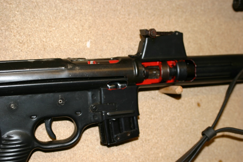
I thought it was time for another cut away rifle that would be interesting. Most people never have the opportunity to see a STg45 much less the cut away version. Enjoy the pictures.
This is a picture of both the 06 and 06H (STG-45)
This is the first of the roller lock non gas operated rifles.
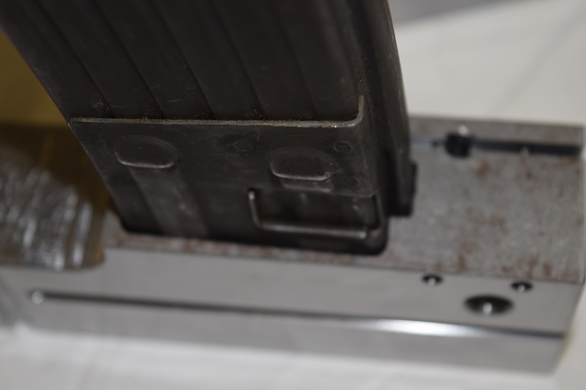
The next machining operation has been completed on the trunnion. This is one of the many unexpected problems with reverse engineering a component. The magazine did not fit. An error occurred that was missed. It is a good thing to check after every step which we do.
You can see the differences here and it is quite obvious. New measurements were taken and the trunnion was re-machined. These are the first two corrected trunnions that have been completed through operation 5.
In this picture you can see that the dimensions are a great deal closer. The thickness on the front of the magazine well are due to the new models not having a bevel put in yet.
Only the rough cut is accomplished in operation 5 on the under side below the barrel. It will be finished in operation 7.
The gas pistol supports.
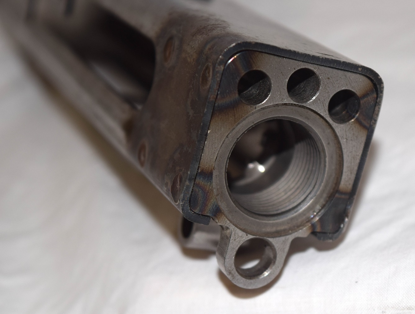
This is the fit and finish in an original trunnion.
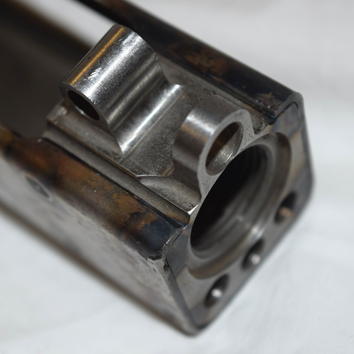
our trunnion.
different angle of the same trunnion.
The first two with magazines in them. These are the minimum and maximum magazines that I own.
With the completion of operation 6 the magazine will set lower. With any luck operation 6 will be this week, however the HAAS team will be here Thursday for routine maintenance.
Here at Gun Lab we do a fair amount of reverse engineering, most of what we like to make have no drawings. However when there are drawings or solid models available we will use them. With this said I have found that most of what is available on the internet or in books is just not correct.
A case in point is the MP-44 trunnion. I have all the drawings that I have been able to find on this part, a number of different sets are out there, and when compared with the actual part have found them to be lacking. Some are just wrong and in some cases I don’t think the person has actually looked at a part.
Over at weapons man he had a write up about reverse engineering a while back.
http://weaponsman.com/?p=21915
It was a very interesting write up and I recommend reading it.
Now back to the MP-44 trunnion. We were contracted a while back with making a limited number of new trunnions for the MP-44. He sent us a very good original one and we had a poor copy of one at the shop. Using these two pieces we started the project of reverse engineering it. The easiest thing to do was look for engineer drawings off the web. These are the ones that I found.
The measurements have been removed from these copies, however you can find them on the internet. I did use the basic drawing as a starting point. The sheets were cleaned and measurements were taken using a cmm, micrometers and pin gauges. Tolerances were set using not only the trunnion but also matching parts. When there was a doubt other parts were located to increase the measurement standards. This allowed us to come up with a reasonable solid model that we felt was accurate enough to start programing.
Even with this solid model and prior to making the parts we still caught a few errors that have been corrected.
Now comes the portion of the project were we start working on the machining of the part. A master cam programed was written to run the trunnion on the cnc machining center. It was determined that 7 set ups would have to be done to machine this part. This is a video of the master cam operation to complete operations 1 through 4.
With the program checked out we then ordered the proper tooling and set up all the off sets on the machine. Test material was brought in cut and machined to size to do a test run. This is the progress so far.The material was saw cut to size.
Then machined to the proper size and squared.
The first 4 ops have been completed. Op 1 and 2 cut the groves on both sides and drilled the ejector holes.
The next phase was op 3 and 4.
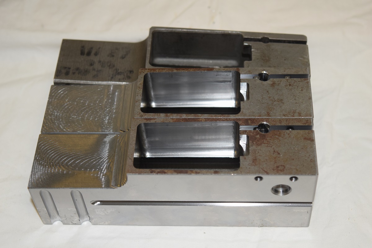
The parts are set up in the vises ready to machineThe barrel hole drilled and machined.
The hole for the bolt carrier is drilled, machined and then bored to a very nice finish.
The gas tube support is machined in.
The first six test pieces.
Even now we are still not working on the actual parts. These are 6 test pieces that will be completed and set to the buyer to test on his kits to verify proper fit. In this case because of tolerances we went with a smaller bore diameter for the barrel fit, it is easier to remove metal then to add it.

 Close up of the support blocks. There are six of then to support the router off of the frame and wood cover. The holes on the end of the block is to allow us to bolt the router to it.
 Another view of the support block set up.
 All the wiring will be changer and run in cable supports.