Over the last few weekend I have been working on trying to get the CNC router completed thus allowing me to finish the stocks and hand guards for the VG1-5 rifle. For every step forward there seems to have been 3 steps back. It is hard to believe that it has been over a year on and off that I have been working on this machine and just when I thought I was finished along comes another problem.
So lets start this long story.
It started with getting the router home and actually operating it. There were some problems noted right off. The first was the table that it sat on. There was way to much vibration for any kind of accuracy. These are the pictures of the old frame.
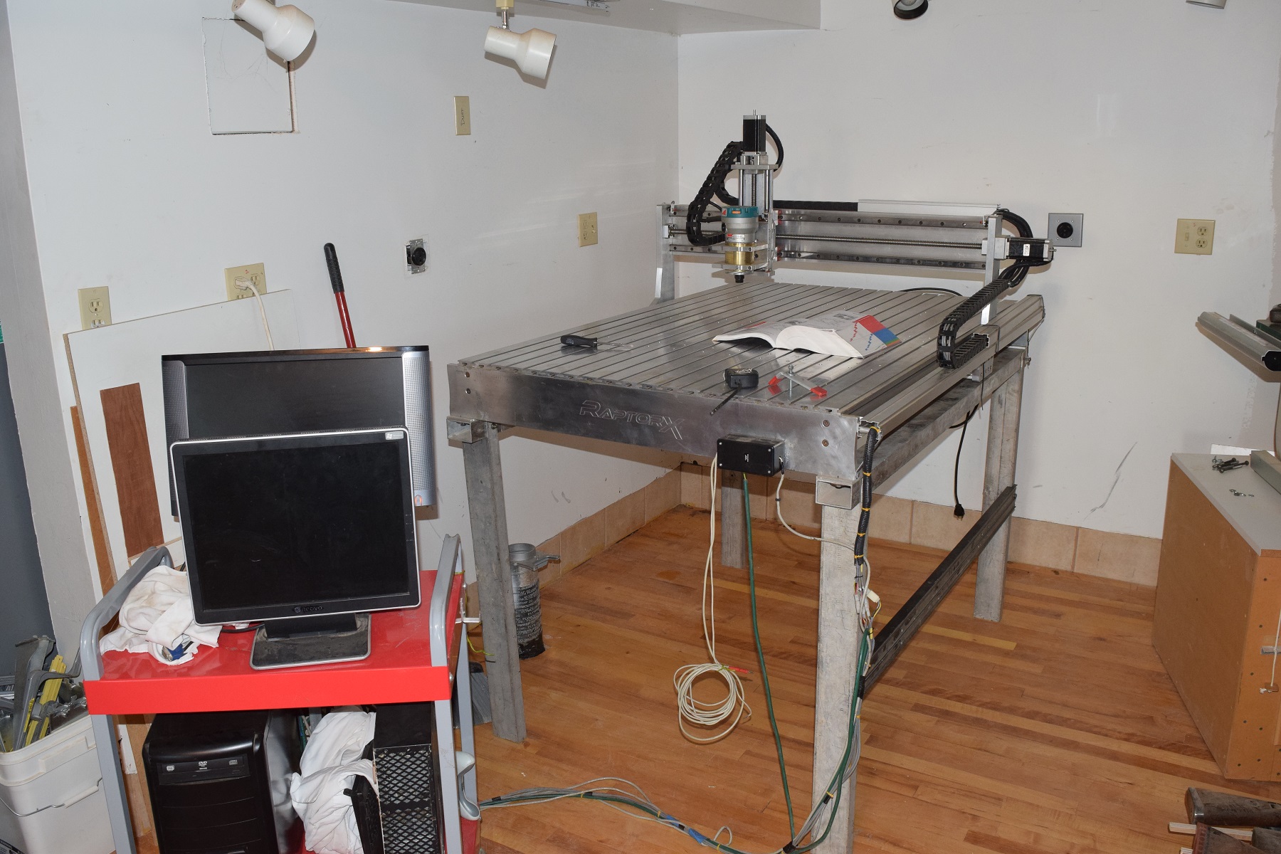

 Parts of it were old window frames
 So a new frame was design and built for the router. 80-20 aluminum extrusions were machined for the frame.
 The table was assembled.
 Custom supports were made to hold the cnc router on the table.
 Now it was ready to move the router over.

 Angle brackets and supports added to reduce vibration.
 The next issue that had to be dealt with was his wiring. It was a disaster.

 While the machine was able to operate there was no accuracy and no way to trouble shoot problems. It was then decided to make an entirely new control panel.

 Everything had its own place and wiring could be traced out to locate problems.
We also changed out the break out board to a smoothie board.

At this point you would think everything would be easy and simple and I could move forward quickly. That would not be the case time and again. Problems started showing up fairly quickly. From simple items like changing from plastic side panels

to aluminum. This helped with the strength and well as allowing allowing a method of attaching components.

 The next issue that came about was changing the limit switch brackets. The builder used strips of bent aluminum that would actually move every tine the X,Y or Z axis touched then.

 Two of them were actually tie-wrapped in place.
 New mounting brackets were made and installed.
 These were machined from aluminum stock to allow no movement.


 However when it came to the Z axis we decided to go with micro switches instead of the push button type.
 This may be an option for all the limit switches in the future.
The next item on the list was the wire troughs. The previous owner used on 1/2 lengths of flexible wire troughs then he used an aluminum cover that he glued and tie-wrapped on the housing.
I bought some more the the original wire troughs and attached it properly to minimize movement.

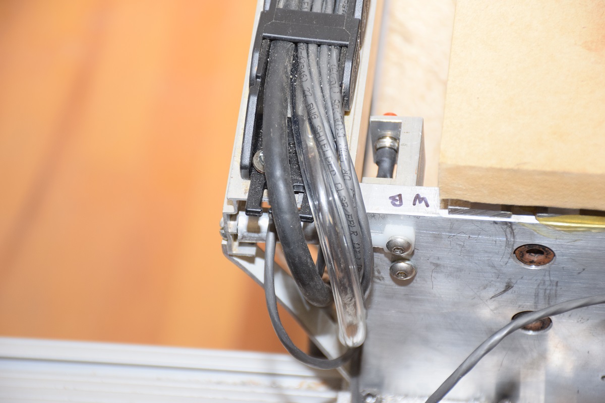
 The final task will be to tie-wrap them all down.
An air system was design and added to the router.
From the regulator and filter.
 To the solenoid switches and manifold.
 The power was run to a plug in box as well. In addition a couple of extra control circuits were added to allow for added features.
So now comes the moment of truth. We had already,with the help of Walley, tested the X axis motor control. With the limit switches wired in and the other axis wire up we were ready to calibrate the router. As one final test I was operating the Z axis with a battery operated drill motor when all of a sudden it just fell off. I mean to say that the complete drive assembly just dropped. This is when we noticed a completely new set of issues.
To attach the ball lead screw to the motor coupler he cut the threads off.

 Then he used the coupler to act as a thrust plate and attachment to the motor. Off course to do this he needed to grind the heck out it as it wanted to rub against the housing.
 He then cut the motor shaft to allow everything to go together.
 You can see just how much of the shaft he cut away.
 This is what he started with.
 To correct the Z axis problems it had to be redesign.

 Still using the original spacer which was way to short.

 A new spacer and housing was design and machined.


 This new housing will allow for a correct height for the shaft, bearing, thrust block and coupler.
This is it for now as we wait for the new ball lead screw. This is also the last 3 weekends of work, not to include the fab shop and library addition. more on those later.
Leave a Reply